Ademco - 1021-12 & 4021-12 Residential Alarm Systems

File Preview
Click below to download for free
Click below to download for free
File Data
| Name | ademco-1021-12-4021-12-residential-alarm-systems-0182395647.pdf |
|---|---|
| Type | |
| Size | 1.98 MB |
| Downloads |
Text Preview
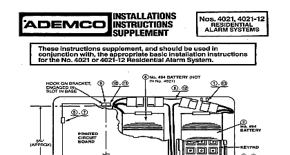
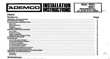
INFORMATION FEATURES DESCRIPTION LED indicators AND WIRING Connection P s CHECKOUT An Burglary System Disarm Burglary System Test Fire System Burglary System Initiate Panic Alan Manually Initiate a Fire Alarm and Visual Indications SYSTEM OVER TO SUBSCRIBER SPECIFICATIONS 1 SIREN SPEAKER CONFIGURATIONS 2 1021 RESIDENTIAL ALARM PROCESSING CENTER 3 4021 RESIDENTIAL ALARM PROCESSING CENTER 4 5240 REMOTE COMMAND STATION 5 No 5240 ARM DISARM CODE PROGRAMMING 6 SYSTEM FIELD CONNECTIONS 7 ALTERNATIVE ARM DISARM CONFIGURATION USING KEYSWlTCH ES PUSHBUTTON S INFORMATION typical Residential Alarm System installation includes a No 1021 4021 type Residential Alarm Processing Center and a of four No 5240 Digital Keypad Stations including the one preinstalled in the No 4021 No 1021 4021 Residential Alarm System monitors all inputs and generates appropriate output signals lt provides supervised zones of burglary protection a supervised fire zone and a twenty four hour emergency circuit silent emer or audible panic It also provides zone status and alarm memory indications The entry delay may be reduced to A built in speaker in the No 4021 provides audible alann annunciation No 5240 Digital Keypad ion s status indication A silent or audible emergency panic alarm may also be triggered and the Interior zone may be OFF and then ON from the Digital Keypad Station s A built in buzzer provides audible trouble annunciation Early production No 5240s with no RED jumper provided on their circuit boards may not be used with the No keyswitch es pushbutton s may be used for arming disarming either alone or intermixed with key stations at a maximum of 4 locations Although these instructions primarily discuss the use of keypad arming dis Diagram 7 indicates how keyswitches pushbuttons may be used Note that a No 706 Mini Howler will be for pre alarm warning entry delay and fire trouble signals if keyswitches pushbuttons are used arming and disarming of the system as well as providing arming disarm FEATURES arming The system may not be armed v h any of its zones in a faulted condition If the fault is not cleared and attempt to an the system is made a 3 second audible warning tone will sound arming disarming with four digit aning and four digit disarming Zone with delay feature Delay times may be set to 30 or 45 seconds In addition the entry time may be to 0 by operating a switch on the No 1021 4021 This zone accommodates closed circuit contacts two circuit Zone for normal and fast acting open or closed circuit devices hvo wire circuit with end of line resistor Zone for normal and fast acting open or closed circuit devices two wire circuit with end of line resistor This may be turned OFF remotely at the No 5240 within 3 seconds after the system arming code is keyed 24 Hour latching panic input for open circuit switches such as No 219 or No 4023 This circuit may also be triggered the No 5240 by pressing the l and keys thereon The panic function is selectable as audible or silent 24 hour fite circuit with LED alarm and trouble indication and audible trouble annunciation at the No 5240 addition a power output for smoke or products of combustion detectors is provided interruptible on reset output triggers for burglary panic and fire status output is available as 6 volts with the system armed and 0 volts with the system disarmed or versa and GREEN LEDs at each No 5240 remote arming point to indicate system arming and loop status respectively siren driver for external speakers with different sounds for fire and burglary audible panic LEDs to indicate the status of each zone Power LED to indicate that A C power is available and the battery is being charged TEST RESET Switch to check the fire system functions alarm cutoff and reset for burglary panic and fire 8,12,16 or 24 minutes DC Power available continuously for powering digital keypad stations etc and interruptible for smoke detectors DESCRIPTION See Diagrams 2 and 3 DELAY ON OFF Switch INSTANT OFF ON on 4621 To set the entry delay to zero move the switch down LED lit To restore it to the selected time move it up momentarily LED out This switch is operative only the system is armed A safety feature however automatically restores the entry delay at disarming time This pre the user from subsequently amring the system and leaving the premises without restoring the entry delay thereby an alarm upon re entry TEST RESET Switch This switch shorts the fire loop to initiate an alarm when momentarily pushed upward to position The main alarm sounder should function giving an indication of battery condition The FIRE TEST is reset operating the FIRE TEST RESET switch momentarily downward to RESET position This downward operation resets fire circuit and smoke detectors powered by the system In addition it is used to clear the memory of alarmin the sys zone status LEDs and in the panic circuit refleoted by absence of GREEN status LED indication at No 5240 local remote keypads Pushbutton a No 4621 option Depressing the BLUE Police Shield pushbutton will activate a alarm The speaker in the No 4021 and external speaker s will be activated loud warbling speaker sound if audible panic was selected For both audible and silent panic a supplemental output trigger will be imme activated Pushbutton a No 4021 option Depressing the RED Flame pushbutton will activate the fire alarm The speaker the No 4021 and external speaker s will be activated loud steady speaker sound immediately as well as a fire indi supplemental output trigger Indicators LED RED This LED flashes to indicate trouble in the Fire zone At the time that this occurs the buzzer in the No will begin to sound intermittently These indications will remain until the fauft is cleared fault could have been caused by one of the following A malfun tion within a smoke or products of combustion detector A break in one of the fire loop wires A break in one of the wires supplying power to detectors A blown auxiliary output current protection fuse interior and Entry Exit Delay Zone LEDs RED