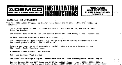
Ademco - 1024 & 1024B Alarm Processing Center

File Preview
Click below to download for free
Click below to download for free
File Data
| Name | ademco-1024-1024b-alarm-processing-center-4358921670.pdf |
|---|---|
| Type | |
| Size | 1.26 MB |
| Downloads |
Text Preview
c INFORMATION Nos and 10248 Alarm Processing zone panic with Superv sed Basic Protection wire Norma I and Fast Acting i meter Shunting with or both basic rotec with 30 Entry Exit Delay Times Hour Emergency Indication Zone Status bell Power and Alarm Memory Bell s Electronic Early Warning Horn Dry Contacts Cut off Restore All Battery Switch I y Vol t supp I Plug in 6 V continuous Built in up to 200 ma Turned ON Stat s 1 OFF from Any SPST Keyswitch be used an Adapter Nos 5073 Nos 244 or 245 No 10248 Alarm Processing The provision an opening cabinets a digital dark No 1024B as No 1024 with permit mounting 5241 The color AND WIRING not connect camp I eted battery Figure 2 p I ug i n transformer i I a I I other w i ring Protection wires End of Line closed g 2 and each zone a a pco 1000 has as series etc quick photoelectric yellow wire wire ON either will 2 unit vibration open circuit Zone open or short when connected use an Ademco No 602 Mat Coupler permissible entry exit ohm End of Line as well path provides seconds permissible WHITE jumper a series wires exit each an as mats may either ohms exit and across ohms 45 seconds cut Fig LOOP AT TOP OF CHASSIS CUT TO SHORTEN DELAY TIMES FROM 45 SEC TO 30 SEC OFF T 1 zzyEzyL STATUS A No 96 12 AT TOP OF L OCEING A CABINET m p m n Ex V 2.5Al 24 HR V AC LET DC CIRCUIT REMOTE STATIONS MAY USED SEE 1 Field Connections MAXIMUM TOTAL LOAD PERMITTED BELL PLUS AUX 6V OUTPUTS IS AMPS 269 parallel as Nos 264 or ON will an emer lcy alarm any output close not cut off 706 Mini Howler shown during open warning case of accidental ON Position single Position No 1024 knockout mounting No 5073 2174 Resistant No 4073 can be seen when The switch may be panel or OFF Otherwise properly Alarm Memory LED which unknowingly are an alarm wi I I not be seen when opening via an adapter 244 or 245 be ACCESSORIES contacts be used as desired p O Dry Contacts digital contacts open upon bell close alarm manually test emergency when emergency contacts V DC units Auxiliary to 200 ma continu can be connected as Nos may be supplied or Photo to 2 amperes alarm and 16 V DC Dells used Electronic 2 amperes auxiliary combined and 20 may be connected electronic emergency minutes cut Fig originally I will any minutes WHITE A larm Memory LED remal ns a dis not ma I V AC Transformer not I I I8 with Molex Red with cabinet an electrical or cold water completed connect CENTER STATUS 2 lndica tors AND CHECKOUT been completed Figure keyswitch OFF wiring connections previous Plug V AC outlet ON 24 hours ddy AC Power LED should ight Observe


