Ademco - 1038 & 1038-12 Contact Indentification Annunciator

File Preview
Click below to download for free
Click below to download for free
File Data
| Name | ademco-1038-1038-12-contact-indentification-annunciator-8642109375.pdf |
|---|---|
| Type | |
| Size | 1.40 MB |
| Downloads |
Text Preview
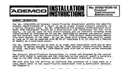
Nos 1038,1038 12 INFORMATION 1038 and 1038 12 Contact Identification Annunciators permit the specific contact identification of a fault in up to closed circuit contacts in a series burglary loop The No 1038 1038 12 CIA uniquely differentiates faults by a distinctive LED indication for the first fault It can be used in new installations and to retrofit e ting alarm by interjection of the No 1038 1038 12 between the control panel and the burglary loop and installation of No Contact Identification Modules with each contact in the loop It can be used with almost any control panel as long as it be supplied with 80 mA of regulated 6 or 12 volts as a function of Model on a continuous basis No 1038 1038 12 can be used as an eight zone annunciator with one or several contacts in series grouped across each fault from sub No 1039 Contact Identification Module or with multiple like numbered No 1039 modules used with one or several series contacts Contact Identification Annunciator control panel burglary loop consists of SPDT relay contacts and or open collector transistor circuits unit also has the ability to indicate the presence of a loop open or a loop short that is not specifically associated with a contact See Diagram 1 armed and disarmed by the control panel with which it operates The interface with Diagram 1 PROTECTIVE LOOP DESCRIPTION CIA Protective Contact Loop Up to eight closed circuit contacts or groups oi contacts may be uniquely identified by unit This loop is supervised and employs a 430 ohm End of Line resistor No 1039EOL There may be up to 100 of resistance in the loop excluding the EOL resistor There may be up to 50 ohms of resistance associated with identified contact e g window foil or group of contacts Response lime The unit protective loop normally possesses a 250 msec response time swingers transients or loop disturbances a glass break sensor vibration contact or other fast responding device is used in the loop cutting the YELLOW ZONE JUMPER on the unit P C board will change ttie loop to the fast response mode 10 msec To lessen the of false alarms the loop should not contain exposed metallic contacts when set for fast response less than 250 msec will be ignored by the unit Contact LED Indicators with memory See Diagram 2 Each identified contact or group of contacts has its own RED for contact or contact group zone annunciation A contact disturbance after arming will cause the corresponding to light The LED will be lit steadily while the disturbance is present AND there is only one faulted contact If the wn is restored or if additional contacts in the loop are disturbed while the original contact is disturbed the LED will flash This rapid flashing denotes the point of FIRST intrusion a second contact is disturbed while the first is still disturbed only the first disturbance uniquely identified The second denoted by the MULTI LED being lit steadily When the first disturbance is restored then the second disturbance will be by an LED lit steadily for that contact When the second and subsequent disturbances are restored within an period their memory of disturbance two or more contacts are disturbed together if at least one is restored the MULTi LED which had been lit steadily flashes to indicate memory of multiple disturbances open in the loop that is not associated with a specific contact or group of contacts that is spanned by a No 1039 Con Identification Module is identified by an OPEN LED that is lit steadily When the open is restored the LED flashes to memory of the open This LED is located behind the flip up shutter on the front of the unit indicated by slowly flashing LEDs short circuit across the loop is identified by a SHORT LED that is lit steadily When the short circuit is restored the LED to indicate memory of the short cilcuit This LED is also behind the flip up shutter the disarmed state there is no latching of memory for previous disturbances All LEDs react to disturbances for a disturbance and off for no disturbance or a restore When multiple contacts are disturbed together only the LED is lit and no unique identification can be provided for the contacts display mode of operation can be selected by the installer It is possible to have the contact LEDs display conditions described in this section or alternatively to suppress any display during the armed state The latter mode is selected by the ORANGE JUMPER This causes the contact and other LEDs to display their current memory status only while the disarmed state Tamper Switch The No 1038 12 is equipped with a SPDT cover tamper switch which can be connected the alarm protective loop for protection during the armed state or separately into a 24 hour circuit that can sense a trouble alarm condition at anytime AND DISARMING of the armed disarmed state of the No 103811038 12 Contact Identification Annunciator is accomplished by control signal from the control panel with which the unit operates The unit can either be armed via a LO Voltage Level and disarmed by a HI Voltage Level Input or oppositely whereby arming is accomplished by a HI input and disarming a LO input cut BLUE JUMPER for the latter configuration A HI input means receipt of voltage 6V for the No 1038 and for the No 1038 12 from the source of the arming signal lieu of a control signal from an alarm panel arm disarm control of the No 1038 1038 12 may be accomplished directly a user operated single pole single throw switch to guard against unauthorized operation use of a keyswitch is sug The switch should be connected across the unit INPUT POWER VIOLET and ARM DISARM leads and the units BLUE jumper should be cut With the switch open the unit is armed With the switch closed the is disarmed of the panel does not clear the memory of open contacts Memory clearing does not take place until the control is rearmed are 2 electronic alarm outputs on the No 1038 1038 12 The OPEN COLLECTOR OUTPUT goes for about 2 seconds every time a detectable change occurs in the loop Detectable changes are a when a contact is b when more than one contact is opened and c when the loop is open or short circuited The OPEN OUTPUT goes low and remains low for as long as there is any fault present of these electronic outputs can be used to activate an onboard SPDT relay by spiicing the desired voltage output with RED flying lead relay coil All three of the relay contact points COMMON N C and N O are for interface one of the control panel burglary circuits A Deluxe Nos 1002,1003,1004,1005,1007,1020 Combination 330342 Series Controls and No 1022 Alarm Processing Centers relay should be activated by the STEADY electronic output and the relay contact should be wired in series a burglary zone on any of these controls The MOMENTARY electronic output should not be used with these controls Processing Centers Nos 1021,1021 12,1023,1023 12,1024,1025,1025 12,1025EX12 No 344 Security Processor and Nos 1034 1034 12 Zone Expansion Centers relay should be activated by the MOMENTARY electronic output and the relay N C COM contact should be wired in in a burglary zone on any of these controls Such connection will permit the Contact Identification Annunciator multiple sequential alarms to the control that it is supporting The STEADY electronic output should be wired to the Output point in each of the supported controls Loop Status Post on Nos 1021,1021 12,1023,1023 12,1024,1025.102512.10250 12 Terminal 16 on Nos 1034 and 1034 12 344 Nos 4080,4080EU 408OXL 4080 12 relay should be activated by the MOMENTARY electronic output and the relay N C COM contact should be wired in in a burglary zone on any of these controls Such connection will permit the Contact Identification Annunciator multiple sequential alarms to the control that it is supporting The STEA