Ademco - 1350 Wall Outlet Photoelectric System

File Preview
Click below to download for free
Click below to download for free
File Data
| Name | ademco-1350-wall-outlet-photoelectric-system-9805431762.pdf |
|---|---|
| Type | |
| Size | 1.28 MB |
| Downloads |
Text Preview
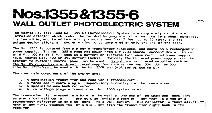
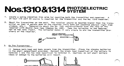
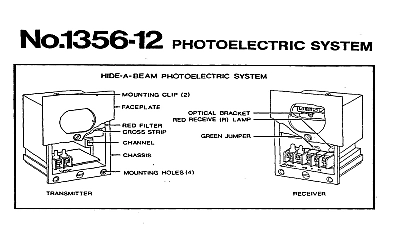
0.1350 WALL SYSTEM Ademco Wall Outlet feet No 1350 will 50 electrical cannot used below main combination control special Receiver compact wal I out activated outlet will ng I match OFF Combination electrical projects any kind made Combination Receiver beam of wall a hol wall aimed at a wall Transmitter a filter Control contains regulated on Control as a closet connected pilot pilot Pilot a solid when OFF when can be compact means of both Combination voltage AC fails pilot rechargeable broken any out of the way also monitors un a 115 AC power control and Combination must be used on any single ever numbers matched to 6 are attached sure each set numbers TO SELECT THE LOCATION FOR THE COMBINATION TRANSMITTER RECEIVER 8 BOUNCE BACK Transmitter Receiver Not Bounce Back Transmitter Receiver whose a hollow at unit 30 a standard with placed a point Make sure are at beam between Combination no possibility feet Bounce Back unit THE CONTROL PACK Combination Mount Control any out of the way cable unit THE LEADS TO TOUCH EACH OTHER AS BATTERY DAMAGE MAY OCCUR Connect black No 295 green Transmitter Receiver and Control and connect and 22 gauge No 289 VAC outlet end and 6 Control plug intransformer Transformer other Control of unused white should Make sure day Make sure circuit offices VAC outlet uninterrupted OFF since not a switch day pilot not aligned hours by NOT black bottom cut or a nearby HEAD THE COMB I NAT I ON TRANSM ITTER RECE I VER or other a guide a template with pencil wall sure opening clear are between a 4 x 2 3 8 other material wall saber marks at each made outside few wall cable hang out of opening up wall of when mounted screws mounting outside be align mounting outside backup color wires end of bottom and backup evenlyso hold much wall wall on protruding mount outside backup not damage wall screwed wall PLATE HEAD PLATE WALL AND ALIGNMENT PROCEDURES properly seen when ON when aligned near be connected aligned easy Bounce Back PILOT LIGHT on goes OFF when seen by temporary Control beam lot can broken other temporary enough No 22 gauge wire go Control Transmitter Receiver wire only end of a 6 volt wire 22OW 6 volt and 4 on and 10 on Control assembly Control THE COMBINATION TRANSMITTER RECEIVER THE REFLECTOR AS FOLLOWS With premises No 440 beam brighter


