Ademco - 216-12 Adapter

File Preview
Click below to download for free
Click below to download for free
File Data
| Name | ademco-216-12-adapter-5614083729.pdf |
|---|---|
| Type | |
| Size | 1.38 MB |
| Downloads |
Text Preview
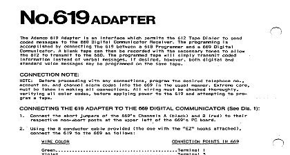
for Digital Remote Stations with Panic Circuitry LED indication with No 21542 Remote Station s LED indication with No 5212 Remote Station s INFORMATION No 21612 Adapter when used with No 21512 or 5212 Digital Keypad Remote Station s permits coded ON OFF ARM DISARM control of 12V alarm panels such as the Nos 102 12,102312,102512 and Alarm Processing Centers and Nos 406612,406OEU and 4090 LogiCenters No 21512 Remote Station provides single LED indication of the status of the control burglar alam circuit two wires are required to connect up to four stations to the control No 5212 Remote Station provides two LED indication a third LED on the station is for another application requires tour wires for connection of up to four stations No 21512 Adapter is shipped connected for QUICK ARM single digit arming and four digit disarming Full 4 arming may be selected by cutting the GREEN jumper on the No 21512 See WIRING Step 3 2l512 AND 5212 Digital Remote Stations are for INDOOR use only twelve pushbutton keypad on each remote station enables the user to arm or disarm the control or initiate a alarm at any time Status of the control burglar alarm circuit s such as ready for arming for arming or is indicated by a single RED LED on each No 21512 and by RED and LEDs on each No 5212 used An audible warning indicator is built into each remote station for use with control entry exit delay circuit and other system warning sounds as the control or its other accessories provide see instructions accompanying those units desired momentary type normally open emergency panic switches e g No 219 may be connected across remote stations YELLOW AND RED leads instead of switches separately wired to the panel unless the stations panic alarm feature is not to be connected See INSTALLATION AND WIRING Section PANIC ALARM connection option can be used which utilizes the No 21612 panic circuitry to trip digital communicator e g No 669,676 or 693 or dialer e g No 612 A silent alarm can then be transmitted a remote location when the appropriate pair of buttons on a No 21512 or 5212 Remote Station or a panic connected to its circuit is pressed The special connections required are incorporated in the INSTALLA AND WIRING Section herein No 21512 Adapter housing is designed to clip into the cabinet of the alarm control with which it is used contains a PC board which includes Leads for alann control connections b Wires and Pins for programming the 4 digit code Jumpers for cutting or positioning as required and d Terminals for Reset and remote station con tamper switches are needed in the remote stations as the system is inherently secure A full four digit code required to d am the system and that code cannot be determined at any remote station A Only No 21512 or No 6212 Remote Stations up to 4 may be used with the No 21512 Adapter Circuit safeguards will prevent arming or disamring by erasing all prior information entered via the if a an erroneous digit is entered or b more than approximately 3 seconds are taken to the code Other remote stations e g Up to 4 Nos 246,246R or 5246 may be simultaneously but independent connected directly to No 40 12,4080EU and 4096 LogiCenters A stand alone keyswitch cannot be used for ON OFF control of the panel when the No 21612 is used an alarm processing center AND WIRING See Diagram 1 to four No 21512 or 5212 Remote Stations may be connected to the No 21612 in partillel indoors on one or wire runs originating at the control where the No 21612 will be located wire size to be used for the entire length of a wire run depends upon the distance from the control to the remote station on that particular run Use the following tabulation to determine the wire size s needed the proposed run s Twisted pair is recommended for greater immunity to unwanted induced voltages DISTANCE TO REMOTE STATION feet 18 Alternatively No 295 4 conductor cable can be used NO TWISTED PAIR No 21512 No 5212 No 289 289 No No 283 2 2 No No No 283 282 a 102512 or 1025EX12 Alarm Processing Center is being used the remote station used at opening time be located so that the ALARM MEMORY LED on the the alarm processing center can be viewed at open time before the panel is disarmed this LED will be lit if an alarm has taken place during the armed period relevant to other controls shown as they have alarm memory by zone after disarming Locate the remote station s where the buttons are not likely to be depressed accidently as this lead to spurious am if single digit QUICK ARM is used or false panic alarms emergency panic alarm can be triggered at any No 2l512 or 5212 Remote Station by momentarily pressing buttons marked and l simultaneously If use of this feature is not desired the No 216 12 VIOLET lead may be left disconnected from the con unit during installation See Step 8 in the following procedure the Remote Station s and run the wiring between them and the control as described above Connect remote station leads as shown in Diagram 1 Connections to the No 21612 Adapter to be installed the control will be made later In each No 5212 Remote Station used CUT THE BLUE JUMPER desired connect any number of momentary type N O emergency panic switches e g No 21.8 across the and N S If the Remote Stations panic alarm feature is not to beconnected as described earlier emergency the remote station s switches may onl be connected on separate wiring to the control panel in the standard man for audible panic a amr or directly to a digitalcommunicator Step 8 SILENT PANIC ALARM is used see the cover from the No 21812 Adapter grasp the cover at the wiring opening and pull firmly and pro its PC board as follows Select a four digit code The code may consist of any 4 different digits from 0 to 9 e g 2 1 5 8 containing repeated digits such as 4 3 3 7 or 6 5 4 6 cannot be used Place the four wires on the appropriate pins The BROWN wire should be placed on pin corresponding to the first digit in the selected code e g Pin 2 if 2 1 5 8 is the selected Similarly the RED ORANGE and YELLOW wires should be placed on the pins corresponding to the 3rd and 4th digits respectively All four wires must be connected for proper operation Full four digit ARMING may be desired as well me system normally will arm upon the pressing of only the digit of the programmed four digit disarm code at a No 21512 or 5212 Remote Station This is par useful if the system will normally be armed by personnel not authorized to have knowledge of the four digit disarm code however full four digit ARMING is desired cut and remove the 2 GREEN jumper from the No 21612 board The system will then require the full four digit code to be pressed before arming takes place If a LogiCenter or No 1021 12 APC is being used cut the 4 jumper on the PC board and tape the ends DO NOT DISTURB THE FACTORY ADJUSTED POTENTIOMETER ON THE No 216 12 PC BOARD 12 The BLUE jumper in the No 216 12 should be on the pin at position in Diagram 1 when the No 216 12 used with one of the APCs shown and on the pin at position when used with a LogiCenter Disconnect the control battery and AC power Connect the remote station wiring to the No 21612 observing the as shown in the diagram Allow slack to reach the final position the No 216 12 will occupy in the control The cover of the No 21612 is provided with a mounting lip which can be slipped over the edge of the cabinet during Step 7 without interfering with