Ademco - 244-12 Two Wire Remote Station Adapter

File Preview
Click below to download for free
Click below to download for free
File Data
| Name | ademco-244-12-two-wire-remote-station-adapter-8976214503.pdf |
|---|---|
| Type | |
| Size | 1.15 MB |
| Downloads |
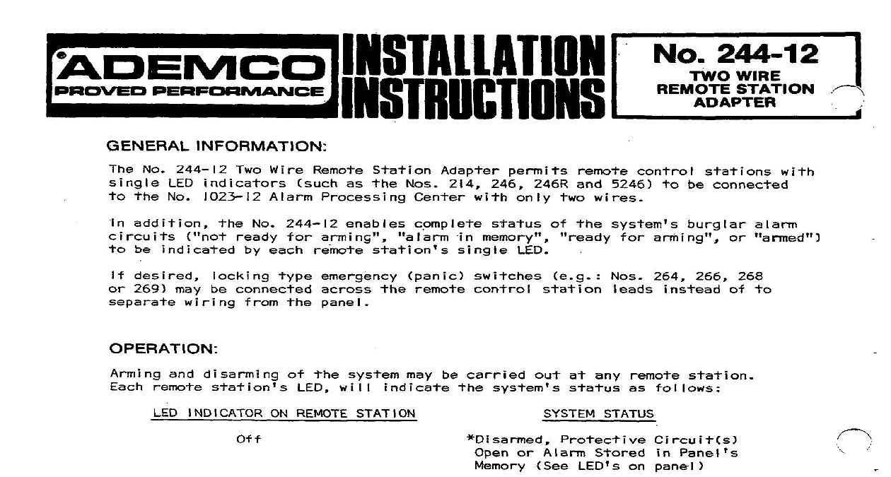
Text Preview
A EMCO NON i INFORMATION No 244 12 indicators No 1023 12 Alarm Processing Wire Remote Station Nos 214 246 and 5246 be connected wires addition be No 244 12 each memory desired 269 may be connected ri ng pane I 264 266 disarming may be carried at any will INDICATOR ON REMOTE STATION STATUS Steadily or Alarm Stored LED on panel Panel Arming Alarm panel Alarm Processing is wi I I memory may be armed directly which of and disarm and No 1023 12 Alarm Processing and may be armed even not delay a or both of the No 244 12 used Alarm stand alone No 244 12 used used ON OFF control panel specia care observe panel AC POWER LED dai I y to make sure and WIRING See Diagram 1 No 244 12 will control I ay zone protected to 4 single remote parallel security used on one or more conjunction wire be connected originating all panel not Use wire be used determine s I Twisted a two wire depends wire unwanted DISTANCE TO REMOTE STATION NO PR I Disconnect panel AC power Place cabinet below No 244 12 mounting ip can be slipped unit be placed any convenient Connect of No 244 12 provided shown Diagram Audible Alarm No 244 I2 shown Diagram Also Step 8 below Silent below Alarm No 244 12 panel shown described Diagram a digital Connect a Splice No 244 12 lead one of wires each wire be made wi I I be the negative Connect other wi II be of each positive wire RED lead of No 244 12 At each wire are sure positive and negative and points Three No 8066 Diodes No 244 12 Wire Adapter each 8066 Diode shown connect Nos 246 or 5246 wire terminal shown each non tampered shown diode already 214 1023 12 P ROCESSING CENTER SILENT ALARM ALARM WIRING WIRING 244 12 TwO WIRE 244 12 TwO WIRE STATION ADAPTER STATlON ADAPTER STATUS STATUS HAND POST PAIR IS RECOMMENDED SIZE DEPENDS ON DISTANCE FARTHEST REMOTE STATION TABULATION TYPE EMERGENCY PANIC MAY BE CONNECTED TO PANEL STANDARD MANNER OR PARALLEL ACROSS THESE LEADS TEXT 2 l TO ADD REQ NOTE E ZI OF WIRING SECTION REMOk SUCH LED REMOTE NO 214 1 Field Connections USE No MORE HAN 4 REMOTE WITH EACH NO 244 12 ADD 2 WIRE RUN S REMOTE STATIONS REQUIRED SEE NOTE SILENT ALARM WIRING 3 AND 8 desired or 269 may be connected on sepprate wiring e ergency If Silent l w i re s 1 to 264 266 Aiarm digital will been switches described switches connected Step 3 above I emergency be connected panel audible Reconnect panel AC powe r Arm and disarm each station well eac


