Ademco - 4025 Back Box

File Preview
Click below to download for free
Click below to download for free
File Data
| Name | ademco-4025-back-box-9864015273.pdf |
|---|---|
| Type | |
| Size | 1.01 MB |
| Downloads |
Text Preview
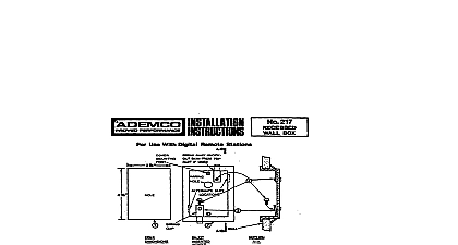
No 4025 BOX use with Nos 4021 and 4021 12 Alarm Processing Centers No 4025 Back Box is provided with securing clips for use in mounting the box in wall surfaces up to thick The procedure describes such an installation In thicker walls the box may be secured in place via 4 countersunk provided in the box flange Cut opening in wall as indicated in Diagram 1 The box itself may be used as a template for determining the size of opening to be cut but cut a V deep notch at the upper left and lower right sides to provide clearance for the secur clip adjustment screws shown in Diagram 2 box 2 G depth permits its installation in wails where 2 x 3 studs are used as opposed to deeper boxes may require the additional clearance afforded by 2 x 4 studs Examine back box and make sure that the clearance between each securing clip and the rear of the box flange the thickness of the wall in Diagram 2 maximum W Remove any tape that may be holding the securing in place Hold both securing clips in position see Diagram 2 and insert box in opening Top flange is indicated in 2 Note If equipment wiring has already been run guide conductors through opening in bottom of box before box in opening Turn each securing clip adjustment screw CLOCKWISE to secure box in opening Securing clips will automati move to position and toward inside of wall as screws are turned Before tightening completely make sure box straight Install any equipment to be housed in the back box e g Digital Communicator Make connections to the wires in wall and route forward the wires to be connected to the control panel Temporarily mount base of No 4021 or 4021 12 Residential Alarm Processing Center to box as follows Remove coyer from No 4021 4021 12 Guide conductors through wiring opening at rear of base Place slots at rear of base over hooks along top edge of box flange see Diagram 2 The narrow horizontal mounting bracket with two hooks that is supplied with the No 4021 4021 l 2 for use the No 4025 is NOT used will not be needed and should be discarded Do not secure the base to the box flange at this time Finish wiring the system first The base of the No 4021 can be unhooked if required to change or check wiring in the back box Secure the base to the box flange with two W 8 32 screws supplied with box Do not substitute longer screws the cover of the No 4021 4021 12 2 1 DIAMETER AND USE AS STARTING FOR CUTTING OUT OPENING 1 OPENING IN WALL THICKNESS a MAX TEXT STEP 2 HOOKS 2 No FLANGE 7 4 FOR MOUNTING FLAT HEAD 4021 1 2 CLIP SCREWS 2 HOLES 2 4021,4021 12 SCREWS PROVIDED VIEW OF No 4025 2 INSTALLATION DETAILS No 4021,4021 12 SUPPLIED VIEW INSTALLED