Ademco - 409-419 Digital Transmitters
File Preview
Click below to download for free
Click below to download for free
File Data
| Name | ademco-409-419-digital-transmitters-7834521906.pdf |
|---|---|
| Type | |
| Size | 1.26 MB |
| Downloads |
Text Preview
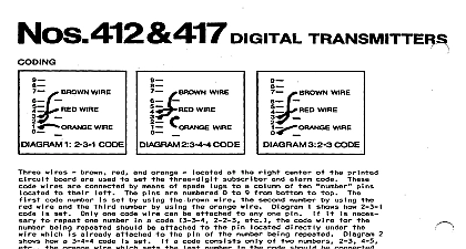
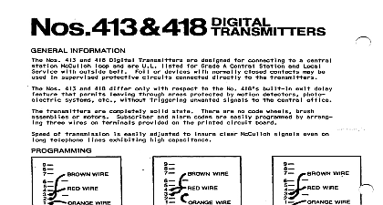
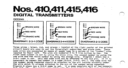
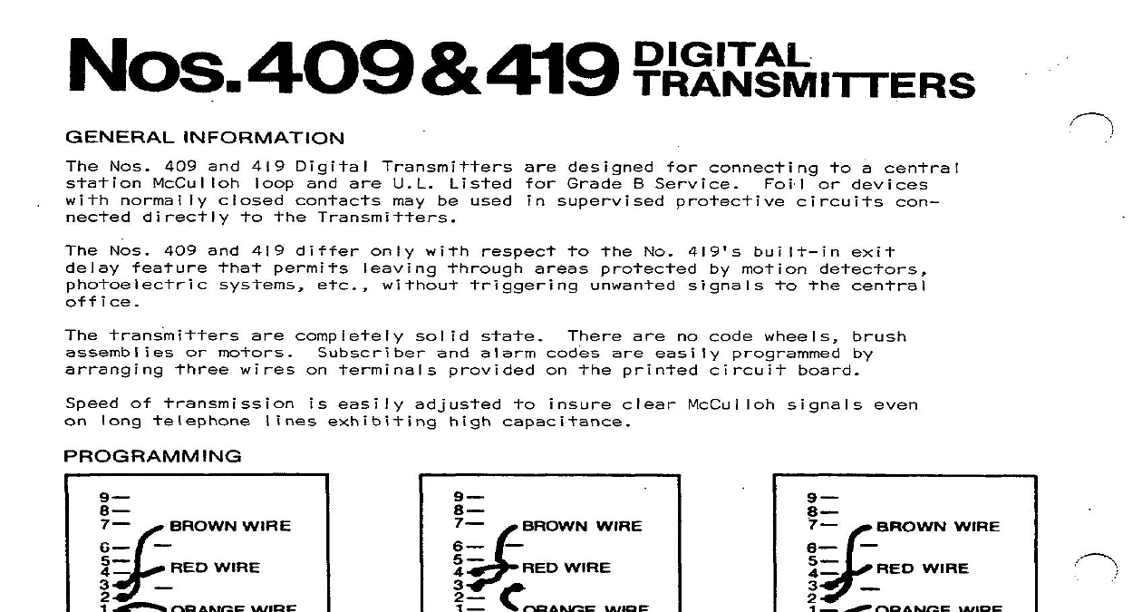
INFORMATION Nos 409 and 419 Digital Transmitters and are U L be used designed Grade B Service supervised a central or devices Nos 409 and 419 differ with No 419 motion motors complete solid and alarm no code wheels are easily printed of easi y adjusted McCulloh e WIRE WIRE WIRE WIRE WIRE 1 2 3 l CODE 2 3 4 4 CODE 3 2 3 CODE WIRE WIRE wi res wires set by using one code wire number how a 3 4 4 1 already brown I i and orange used connected designated set means of spade to 9 from bottom alarm wire printed number wire by using wire by using orange wire shows how a 2 3 l a code be attached attached set a code umn any one pin wire necessary number being pin being should as 2 4 2 3 3 3 also numbers connected orange wire at shows how a 2 3 code set set wire pro PROCEDURES SET open on protective unplugged closed alarm and off out protective depressed called RECEIVER PRINTER RECEIVER WI LL NOT WORK AT ALL LAMP TEST AND NO POWER ON LAMP WILL NOT PICK UP ON INCOMING WI LL NOT G IVE To COMMUNICATOR WILL NOT DISPLAY MESSAGE WILL NOT GIVE HANG UP SIGNAL COMMUNICATOR ACTIVATE PRINTER I WITH TWO RECEIVER OPERATION THE MONITOR MODE MASTER A SLAVE HANGS UP ON INCOMING COMMUNI CHANGE ON DISPLAY WHEN SILENCE BUTTON IS DEPRESSED 1 NO 660 RECEIVER WILL ONLY PROCESS ADEMCO 8 SILENT KNIGHT AND POSSIBLE REMEDIES see Power On Check wal I outlet 24 hour outlet not 110 V AC certain outlet ine cord ohms Next meter male plug R X IK scale volt ohmmeter R X 1 scale check prong Check No 660 Check phone block i nes No 8115 cord milI iamp approximate milliamp meter No 8115 direct R X 1 scale and green wire ohms head of solderless place short No 8115 No 8115 c No 90 2 FUSE AMPS 409 419 JUMPER CUT FOR ROUND EXIT CODE AND WIRING BOTH UL SLOW AND FAST MUST RlJN TO ALL PARTS OF THE CIRCUIT 3 1320 ACTING ACTING A NOT INSTALL FUSE OR TO TELEPHONE LINES OTHER WIRING HAS COMPLETED 4 Using Built in Power Supply U L INSTALLATIONS BOTH I AND OF THE CIRCIIIT BE RUN PARTS OF PROTECTIVE LOOP 90 2 FUSE 409 419 11 11 II RED CUT LINE SUPPLY BATTERY t 1 DC MIN V DC MAX 5 Using End Of Printed DETECTORS NOT INSTALL FUSE OR TO TELEPHONE LINES OTHER WIRING HAS COMPLETED Power Supply mounting must be black Board pre wired Wire or 5 series each be used open series an alarm shown a short be either as vibration Supply Diagram photoelectrics as series and 6 door and 5 permissible connected 225 ohms Separate permissible Supply of Diagram protecti 225 ohms shoz