Ademco - 412-417 Digital Transmitters

File Preview
Click below to download for free
Click below to download for free
File Data
| Name | ademco-412-417-digital-transmitters-3572149860.pdf |
|---|---|
| Type | |
| Size | 1.20 MB |
| Downloads |
Text Preview
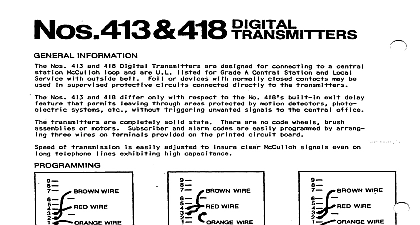
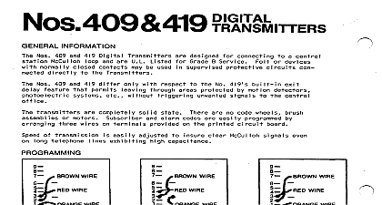
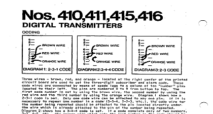
Nos 412 417 DIGITAL TRANSMlTTEqs WIRE WIRE 1 2 3 l CODE 2 3 4 CODE 3 2 3 CODE WIRE WIRE number wi res wires wi re and being which how a 3 4 4 set set brown orange used connected set means of spade pins set by using numbered a column alarm to 9 from bottom printed any one pin by using shows how 2 3 l neces wire by using orange w i re be attached a code attached pin one code wire number already set orange wire which bottom at pin of a code consists number pin being numbers connected shows how a 2 3 PROCEDURES Set The Transmitter at Closing Time properly order ON up be closed set entire will be transmitted on may be the Protected Premises 412 when protective when No 412 will one additional he closes sent exit and subsequent 417 way out during motion No 417 when No 417 wJl protectivecircuit period approximately pass seconds signal or other armed and at end of subsequent close door end of three STRIP AND WIRING 4 Supply U L CIRCUITS MUST BE RUN TO PART OF THE PRO I VE LOOP AND 5 Of Line Supply U L CIRCUITS BE RUN TO EVERY OF THE PROTECTIVE AND 1 1320 DO NOT INSTALL THE FUSE OR ATTACH THE TELEPHONE UNTIL WIRING HAS BEEN COMPLETED ACTING LINES DO NOT Of THE Fl UNTIL WIRING HAS BEEN COMPLETED OR ATTACH THE TELEPHONE LINES THE PROTECTED PREMISES the 417 as opens additional will sent either will sent No 4 door or closed closes normal tr ansmitted day CONDITION an No 417 window door and protective will transmitted either No 412 mounting must be black I ternat vely cabinet permit eads must be connected pry off protective short shows connections acting built in wires connected protective 225 ohms as supply will as photo used supply volts No 1320 built i plugged shows connections at On U L an volts end of used 225 ohms voltage nickel 2 and plugged provided power charge on 24 hour soon as connected be a discharged plugged WAlT AT LEAST MlNUTES BEFORE Ademco No 90 2 send a round connect does wait now be above and completed should grounded be connected THE CIRCUIT STAYS ON STEADILY TRANSFORMER SHOULD BE UNPLUGGED SYSTEM FAULT THE STANDBY OF TRANSMISSION which of a code can be adjusted printed potentiometer be necessary get THE TOTAL TIME REQUIRED FOR SENDING 3 ALARM ROUNDS U L BE LESS THAN 34 SECONDS THE SPEED OF TRANSM ISS I ON ADJUSTED TEST THE TRANSH ll TER TO MAKE THAT THE 34 SECOND LlMlTATlON THE SUBSCRIBER CODE HAS BEEN SELECTED NOT BEEN EXCEEDED