Ademco - 414 Digital Hold-Up Transmitter

File Preview
Click below to download for free
Click below to download for free
File Data
| Name | ademco-414-digital-hold-up-transmitter-0347859126.pdf |
|---|---|
| Type | |
| Size | 1.25 MB |
| Downloads |
Text Preview
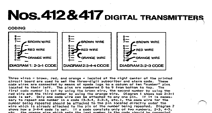
No 414 DIGITAL HOLD UP TRANSMITTER U L central may be used 41 414 Digital superv sed or non superv openor designed closed c i rcu its motor camp iete a state sol codes printed no code wheel easily arranging of McCulioh on WIRE WIRE 9 WIRE 1 2 3 l CODE 2 3 4 4 CODE WIRE 3 2 3 CODE wires 9 from brown used set orange alarm wires designated set by using wire by using orange wire means of spade wire number set shows how a 2 3 l using wire necessary being already wire shows how a 3 4 4 a code consists coi umn set number one code wire a code attached as 2 4 2 connected numbers be attached number any one also 3 3 3 orange wire at bottom should shows how a 2 3 code set No 414 provides used on READY when needed ail opening closing and unit an READY operated out defective or more hold up READY lamp unplugged alarm be at A C on A C being A C should out electrically called checked V AC outlet make sure alarm a transmitted actuated No 414 will when will a non lock in actuated wi I I be transmitted REMOVED FROM ITS MOUNTING SURFACE HOLD UP SIGNAL WILL BE TRANSMITTED wired series THE CABINET OPENED OR IF AND WIRING UL OF THE ACTUATING BOTH RUN TO ALL I G lpc AMPS 90 2 FUSE 414 0 HGLDUP 4 Using Built in Power Supply 4 Wire Supervised Circuit mounting must be temporarily permit Fz 1320 FUSE NOT CONNECT TO TELEPHONE UNTIL OTHER WIRING COMPLETE laced pre wired connect PC Board black PC Wire be used are Hold up No 267 Hold up No 264 Money Clip contacts a non locking 266 Foot Rail or closed Nos 268 and No 414 Wire Supervised either must be run be used as we i will Diagram series preferred open an alarm one 225 ohms On U L all circuit permissible a Wire Supervised V DC preferred used 603 must be battery I i net1 power Diagram I y at normally devices an actuation V DC maximum on U L new power be used as well I y a protective shown Diagram 5 to a normally device series a battery actuating 225 ohms and On U L must be run ail Diagram and 6 as shown 4 to 5 to 6 and circuit not contacts be wired parallel must be added Do not use U L 414 U L INSTALLATIONS BOTH AND OF THE ACTU CIRCUIT MUST BE RUN ALL DEVICES 24 HR MAC a A G nvwur 9 HQ DUP TEL EPtbNE V DC hIIN V DC MAX 603 125 OHM 10 WATT NECESSARY ONLY IF N 0 DEVICES 5 Using End Of Line Supply 2 Wire Supervised Actuating Circuit outlet A C permit No 1320 charge voltage and 2 and plug