Ademco - 425 McCulloh Anti-Clash Adapter
File Preview
Click below to download for free
Click below to download for free
File Data
| Name | ademco-425-mcculloh-anti-clash-adapter-7240519836.pdf |
|---|---|
| Type | |
| Size | 1.05 MB |
| Downloads |
Text Preview
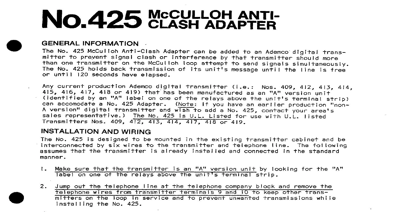
No 425 McCULLOH ANTI ADAPTER No 425 prevent No 425 holds until seconds elapsed be added an Ademco digital attempt signals more current accomodate version No 425 digital 418 or 419 an one of No 425 Adapter w o manufactured an unit you have an earlier a No 425 409 409 No 425 414 U L or 419 with U L WIRING designed be mounted six wires existing already connected be sure an one of unit out No 425 service prevent and to other circuit snapping off Step 8 Phillips standoffs screws No 425 Diagram and screws will used will No 425 VIOLET YELLOW and RED Leads connected Diagram GRAY cover insulator No 425 and No 425 added screws Step DESCRIPTION OF OPERATION below extended No 425 cannot course other connected GRAY leads shown Diagram Step 2 SCREWS WITH STANDOFFS No 425 418 and 419 2 LUGS EITHER C BOARD WITH HAVE POLARITY LABEL RELAY 413 418 FOR REST OF TRANSMITTER SEE INSTALLATION FOR PARTICULAR 1 CONNECTlON OF No 425 TO TYPICAL DIGITAL TRANSMITTER OF OPERATION the McCulloh message hold off send a transmission determine No 425 clear other clear released busy with to a maximum of seconds hold off No 425 senses clear seconds I I be released of ine SPECIFICATIONS 3 8 6.4 cm 3.5 cm No 425 powered digital which volt drop zero No 425 presents all No 425 WITH NO 425 THE CENTRAL OFFICE FAILS TO RECEIVE TRANSMISSIONS THE PROTECTED PREMISES CAUSE The No 425 has not been properly Correct as detailed all correct Diagram wir Be Defective 425 module ine wiring unit properly No 425 ADEMCO for