Ademco - 4275 Passive Infrared Detector

File Preview
Click below to download for free
Click below to download for free
File Data
| Name | ademco-4275-passive-infrared-detector-3649258017.pdf |
|---|---|
| Type | |
| Size | 1.29 MB |
| Downloads |
Text Preview
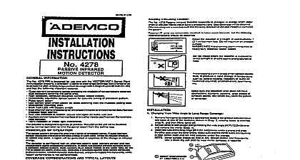
c LINES INDICATE PRINCIPAL CHANGES THIS ISSUE AOEMCO No 4275 Passii motiin detec Point Module is dasignad for use only with VECTOR series sscurity systems It is a versatile unit onering either wide angle or long narrow area protection 2 separate mirrors are supplied The detector sudden and slight changes in temperature PATTERNS Area WI 4 Angle Ylrmf M 13 Ml 1 U I LM Area Long Ranga Minor HINTS Donoth6t6llwhomuu or dimctty the area of detection thus when an intruder Or enters any tone the resulting change in energy is detected and an alarm condition will Best coverage will be obtained if mounting is such that the likely direction of intruder is across the pattern bating unit in mu wntlin 8uch 66 oMtr6l md tom or ducb h06Un Of my kii elr nwn6 approximxtaty 7 the Wtutor on lwln sounow UblbIg moo wrhw CIUIQIIQ From Wtda Angb to Long Range 1 The PIR is locked to the wall plate by a tab that engages a quare opening In the base see Fig 3 The PIR can only be by cover removal depression of the LIFT 1 3 S w BLADE AND TWIST Remove front by insert a screw blade in groove base at the shown Fig 1 rotat blade to snap and then lift cover off Spread either or plastic holding wide angle tt mirror remove the one side the narrow 70 ft under a and snap other side the other mat tfte sides are their ktld under prongs from the inside a small blade and 2 If t he PIR to ba mounted a flat wall with its mounting install a ff4 into the wall the planned sideto of the PIR 1 below the top of ths Leave W between the head and wall Hook the on the wall puncturing iabel and In the mounting on both sides the mirror 2 Mirror surface rhould be free of dirt foretgn and fingerprints Use a clean dry soft to wipe mirror surfaces if required NomalYeuntln Mount the wall plate to a firm vertical surface on wall or tn corner Position the plate so field wirina is oentered in the rectanoular at the top L the plate wall wiring t e no than S 16 diameter See Flgure 3 and A Feed wiring through top access hole of detector foam dmfl protector but do not connect terminal block yet Attach unit to wall plate by engaging all four on the plate into slots on the rear of the and by pressing downward sea Fig 3 wall plate hooks will puncture the label on back of me base Invefted Mounting small pets have l ccedm to the area protected by the thii 8ection pertains detector may be installed approximately 3 ft to 3 H from the floor provided fumitum or other objects do obscure the pattern of protection detector and wall plate must be mounted inverted PIR window at the top with the wall plate tilted downward Two self adhesii been provided to aid in tilting the wall plate must be noted that although this procedure adjusts PIR zones so that small animals wfll not be a cmwling intruder will ALSO go undetected spacers The spacers am to be used with the wall plate when the wide angle mirror is in use the two spacers one abwe the other affix the combination to the rear of the plate in line wfth the single mounting hole at the end of the plate opposite to the entry access cutout Yountlngz ona of the spacers to the rear surface of of the two corner mount tabs on the wall on the end opposite to the wire entry cutout Follow Mounting steps 2.3 and 4 das previously but orient the wall plate so that wire entry access cutout in the wall plate is at the bottom When the detector h mounted in an Inverted that portion of the detector mirror which provides a downward beam of protac will now provide a beam that points upward will apply to both mirrors long range and angle If possible install the de tom so this now upward pointing beam ls not at ceiling areas that Include heating or conditioning duct8 and vents or lighting fix sources cannot bs avoided the If these segments of each mirror should masked to avoid the posaibillty of false alarms indicated in the diigmms hemln Remove the mirror from the detector mferrfng the previous page for Information on mirror Mask the appropriate portton of each mirror as in the dlagmms below Electrical tape masking taps may be used Bi sun to aonr Replace the mirror making sum lt ls secumly position before installing the cover long range applications where the is used to protect narrow corri or where single protectii zones am through doorways or room open the pulse count option must be dis es shown in Fig 4 to provide an alarm response AN ID NUMBER all Identification number the switches on the circuit board The ID is equal to the sum of the switch values in position Each switch has a dfffemnt and should be set according to the following NUMBER 16 6 CONNECTIONS both polling loop wires through the win access near me terminal block and connect to screw see Fig 4 OBSERVE PDURfTVl Count Optlow detector includes Pulse Count circuitry that stability in adverse environments to minimixe alarms This circuitry is active when the switch 6 the circuit board is set to the PULSE COUNT see Fig 4 The detector will then normally an atarm within 3 to 4 steps sIrICe the PNCOSS logic requires mom complex motion than just a event IMPORTANT If the switch on the 4275 address in me VECTOR control must NOT be for pulse count programmed for PUIM COWIt me Corms ON Alarm does not CAUSE temperaturn Change Check electric or gas heaters open electric arcs etc causing drapes light fixtures material to move voltage supplied to detector inadquate reversed or Inopemtive Changes Code mallunction Check for bads fumltum or equipment me wowtad rfaa surface is unstable few degraas of Wrtical shift can range substantiilly address wde protec cleared of all people Diirm PROCEDURES minute warm up is rquired after ap power Testing should be conducted wlth the s stam control during the test procedure to pla reporting of unwanted alarms right posltion Place WALK TEST SWITCH lo walk test right position as shown In Fii 4 front wver and walk through protective zones that the detectots LED lights whenever la detected LED will only be active and should only ba used walk test procedurea When walk Iul b corn PULSE COUNT SW 66 to instant the Instant msponq mode the LED stays for approximately 1 to