Ademco - 453 Remote Ultrasonic Monitor

File Preview
Click below to download for free
Click below to download for free
File Data
| Name | ademco-453-remote-ultrasonic-monitor-3205981764.pdf |
|---|---|
| Type | |
| Size | 1.30 MB |
| Downloads |
Text Preview
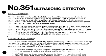
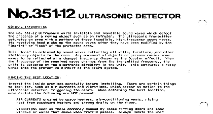
No 453 REMOTE ULTRASONIC MONITOR No 453 Remote Ultrasonic No 453 with No be No 450 and 454 series No 351 accompany motion with or No 351 ultrasonic No 351 protected No 351 12 provide not pinpointing area an ultrasonic each detector subsequent No 453 can be and 2 permit optional detector s ultrasonic No 453 not have be connected provide used an aid during Diagrams con MPORTANT No 453 with be used series 453 monitor YELLOW jumpers boards a on cut Diagram Diagram No 450 and be both YELLOW jumpers have YELLOW jumpers No 453 contains may be monitored meter GREEN and RED area meters LED a two position of ultrasonic monitored meter divided motion any Scale Division none Alarm protected alarm may occur RED may detector motion high upper of RED and Swi tch position switch a choice action position Zone wi I I will off when le he ultrasonic no disturbance position LED will switch zone will moved ultrasonic FOLLOW position after disturbance AND WIRING wiring screws and place mounting provided shown diagram wiring pro PAY PARTICULAR ATTENTION TO THE DIAGRAM NOTES ABOUT JUMPERS potentiometer I 4 I 4 6.4 3.2 AC from No 1320 Plug in not power be used power No 453 other circuit ultrasonic may any equipment take off DO NOT DISTURB NO 1320 TRANSFORMER AC 24 HR OUTLET USE OR OTHER EOLJIPMENT ULTRASONIC OR CIRCUIT M SAME SCR 3 connected ohms or more SCALE LITTLE OR NO DISTURBANCE CONDITIONS SENSITIVITY HIGH DISTURBANCE LEVEL Y MONITOR AN ULTRASONIC AS ONE SERIES THE No 450 or PLACE JUMPER ACROSS F IELD CONNECTIONS SEE DIAGRAM FOR CHART RECORDER monitoring 450 and 454 series BOTH with all other JUMPFRS PRFW series uni s 8 be used with 453 RECORDER 1 1 NOTATION DC TO 120 MA AT 9V l USED I I CONNECTIONS HZ CONNECTION OPTIONA L RECORDER No 453 1 FAIL TO WHEN ATTACHED DETECTORS ARE PICKING UP MOTION CAUSE U I trason properly up c Detectors AND TESTING pro open or shorted wirinq missing unit power of 12 V AC across see securely No 1320 Transformer 24 hour outi t shorted 2 ALWAYS HIGH RED ZONE OR IN GREEN ZONE ALARM CONDITION CAUSE properly may be due SYSTEM for ic Detectors nvo I ved TURBULENCE or broken No 453 Check wiring out No 453 3 REMAINS LIT AT ALL TIMES CAUSE switch Move switch meter move back position LED should zone Relocate picking per a high tur mild unit high pro air Ultrasonic i se not of using ul unused GND and SIG unused NOTE REMINDER To assured are aware proper