Ademco - 5240-12 Self-Contained Digital Remote Station

File Preview
Click below to download for free
Click below to download for free
File Data
| Name | ademco-5240-12-self-contained-digital-remote-station-5936108472.pdf |
|---|---|
| Type | |
| Size | 1.18 MB |
| Downloads |
Text Preview
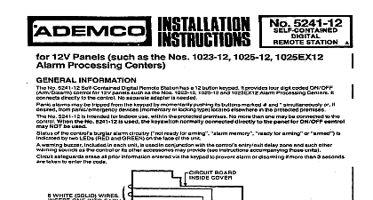
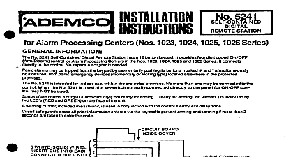
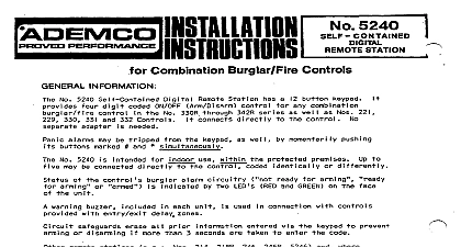
I No 524042 INDOOR Use with Nos 1021 12 and 402142 Alarm System Controls INFORMATION No 5240 12 Self Contained Digital Remote Station has a 12 button keypad It provides four digit ON OFF Arm Disarm control for the Nos 1021 12 and 4021 12 Residential Alarm System Con It connects directly to the control No separate adapter is needed alarms may be tripped from the keypad as well by momentarily pushing its buttons marked l simultaneously No 5240 12 is intended for indoor use withln the protected premises Up to four may be connected to the control coded identically or differently including the unit that is built into the No of the control burglar alarm circuitry ready for arming for arming or bypassed is indicated by two LEDs RED and GREEN on the face of the unit warning buzzer included in each unit is used to provide entry warning fire trouble sounding and arming faulted zone warning safeguards erase all prior information entered via the keypad to prevent arming or disarming if than 3 seconds are taken to enter code PIN CONNECTOR Bend each end as shown before inserting connector WHITE SOLID WIRES ONE INTO EACH HOLE NOT FOR CODE DIGIT WIRES WH wire not used tape end DIGIT WIRES CONDUCTORS 6 2 4 9 HAS PROGRAMMED EXAMPLE SHOWN CODE PROGRAMMING AND WIRING Select a four digit arm disarm code for each of the No 5240 12 Remote Stations up to 4 per con to be used The code must contain 4 different digits do not use zero Digits may not be used than once such as 2 6 6 7 on multiple unit installations may be c d differently each other if desired Programqach No 524 12 for its assigned code as follows Note In the following example the No is being programmed for code 5 2 4 g Remove the unit cover and position in Diagram 1 so that the circuit board within the cover appears as Obsenre the Digit Selection Wires the four 4 inch solid conductor colored wires at the side of the circuit board The colors are BROWN RED ORANGE and YELLOW Observe the 10 pin connector below the right side of the PC board Its holes are associated with values of 1 through 9 and 0 as indicated in Diagram 1 Note that the holes are not numbered Simply insert the BROWN wire in the connector hole which corresponds to the numerical value for the first digit 1 in Diagram l programmed example To insure good contact bend the end of each wire as shown in Diagram 1 before in it in the connector Similarly insert the RED ORANGE and YELLOW wires in the holes for the 2nd 3rd and 4th digits and in Diagram l programmed example Insert the YELLOW wire provided 12 inch length of 24 AWG solid conductor into the hole route the wire out of the No 5249 12 Insert one of the six WHITE wires into each remaining connector hole and dress all wires neatly against the PC board One WHITE wire will not be used Its end should be taped Replace the unit cover until ready to mount it in its selected location UPPER LOWER 10 o 13 o 14 o 6 o PANIC ALARM NOT DESIRED NOT CONNECT VIOLET SILENT PANIC ALARM WIRING STEP 5 5240 l 2 COLORSA BYPASS 1 PANIC INPUT STATUS JTATUS 22 CONDUCTORS No 295 CABLES EQUAL MAXIMUM WIRING 400 FT OF 10 PIN ADD 5240 12 REQ BE PANEL 4021 12 UNIT I A STATION BUZZER IS NOT USED SPLICE GREEN TO ITS OWN LEAD INSTEAD AS SHOWN p 2 FIELD CONNECTIONS Mount the No 5246 12 s in the desired location s and run wiring between it them and the control shown in Diagram 2 Total wiring distance should not exceed 400 ft Do not yet connect the wir to the control Up to 4 No 5240 12 s may be connected in parallel to the control either on the same or runs No 5246 12 s are intended for surface mounting or flush mounting with a No 217 Flush Box WITHIN the protected premises Concealed wiring may enter via a large square hole the base of the unit Breakaway knockouts are provided in the base for exposed wiring wiring between the control and the No 5246 12 built in entry exit warning buxzer unit lead will NOT be required if no warning buzzer is desired In this case splice each unit lead to its own BLACK lead as indicated in Diagram 2 any individual buzzer is to be silenced while others are not splice that particular station lead to its own BLACK lead as described in the previous paragraph Disconnect the control battery and AC power Connect the remote station wiring to the control as shown in Diagram 2 For AUDIBLE PANIC ALARM make connections as shown in Diagram 2 If SILENT PANIC ALARM is desired from the No 5246 12 s connection may be made to a sup output device Utilize the VIOLET lead of the No 5240 s to obtain a positive supplemental output trigger the device using this trigger is not powered from the same source as the control also connect jumper between the control terminal to which the BLACK lead is connected and the negative voltage terminal of the cited device If the panic alarm feature of the No 5246 12 s is not desired do not connect the VIOLET lead s the unused end s Reconnect the control battery and AC power AND OPERATION No 5240.12 will system status via its GREEN and RED LEDs as follows LIT STEADY FLASHING STATUS Protective Circuit s or Alarm Memory Not Not Ready for Arming Protective Circuits Ready for Arming Ready for Alarm or Disarming with Interior Zone Bypassed for Alarm or Disarming Arm and disarm the system at each No 5240 12 as follows and check the response of each LED indicators at least 5 seconds between successive attempts at arming or disarming with the No 5240 12 or it not be possible to successfully enter the next disarm arm code Exception The 5 second wait can be by keying any digit not used in the 4 digit code and then the code the 4 digit code is being entered if more than 3 seconds are taken to enter the entire arm disarm or if the code digits are not entered correctly all prior entered information may be erased thus code entry to be started anew Make sure all protective circuits are intact and the system is ready for arming The station LED should be lit Arm the system by entering the station programmed 4 digit code The station GREEN LED go out and its RED LED should light steadily If the Interior Zone is to be bypassed enter within 3 seconds after the 4 digit code is entered This will cause the RED LED to flash a perimeter or unbypassed interior circuit is then disturbed an alarm will sou