Ademco - 5241-12 Self-Contained Digital Remote Station

File Preview
Click below to download for free
Click below to download for free
File Data
| Name | ademco-5241-12-self-contained-digital-remote-station-3187650429.pdf |
|---|---|
| Type | |
| Size | 1.20 MB |
| Downloads |
Text Preview
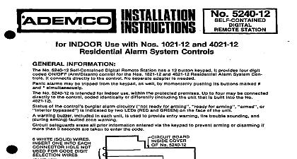
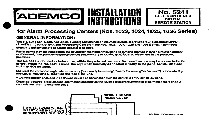
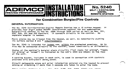
for 12V Panels such as the Nos 1023 I 2,1025 l 2,1025E 12 Processing Centers GENERAL INFORMATION No 5241 l 2 Self Contained Digital Remote Station has a 12 button keypad It provides four digit coded ON OFF control for 12V panels such as the Nos 1023 l 2,1025 12 and 1025EX12 Alarm Processing Centers It directly to the control No separate adapter is needed alarms may be tripped from the keypad by momentarily pushing its buttons marked and l simultaneously or if from panic emergency devices momentary or locking type located elsewhere in the protected premises No 5241 l 2 is intended for indoor use within the protected premises No more than one may be connected to the When the No 5241 12 is used the keyswitch n mally connected directly to the Panel for ON OFF control NOT be used of the control burglar alarm circuitry ready for arming memory for arming or is by two LEDs RED and GREEN on the face of the unit warning buzzer included in each unit is used in conjunction with the control entry exit delay zone and such other sounds as the control or its other accessories may provide see instructions accompanying safeguards erase all prior information entered via the keypad to prevent alarm or disarming if more than 3 seconds taken to enter the code units WHITE SOLID WIRES ONE INTO EACH HOLE NOT FOR CODE DIGIT WIRES DlGtT WIRES CONDUCTORS end as shown before inserting connector 1 CODE PROGRAMMING AND WIRING Select a four digit arm disarm code for the NO 5241 12 Remote Station The code must contain 4 different digits 2 6 3 7 Digits may not be used twice Program the No 5241 12 for its assigned code as follows Note In the following example the No 5241 l 2 is being code 5 2 4 g Remove the unit cover and position it so that the circuit board within the cover appears as shown in Diagram 1 Observe the Digit Selection Wires the 4 inch solid conductor wires at the left side of the circuit board colors are BROWN RED ORANGE and YELLOW Observe the 19 pin connector betow the right edge of the PC board Its holes are associated with digit values of 0 9 as indicated in Diagram 1 Note that the holes are not numbered sequentially Simply insert the BROWN wire in the connector hole which corresp onds to the numerical value selected for first digit in Diagram l programmed example To insure good contact bend the end of each wire as shown in Diagram 1 before inserting it in connector Similarly insert the RED ORANGE and YELLOW wires in the holes for the Pnd 3rd and 4th digits respec and in Diagram l programmed example Insert one of the six WHlTE wires into each remaining connector hole and dress all wires neatly down against PC board Replace the unit cover until ready to mount it in its selected location Mount the No 5241 12 in the desired location and run wiring between it and the control as shown in Diagram 2 wiring distance should not exceed 400 ft Do not connect the wiring to the control until Step 6 The No 5241 12 is intended for surface mounting WITHIN the protected premises Concealed wiring may via a large square hole in the base of the unit Breakaway knockouts are provided in the base for wiring Where the Alarm Processing Center is to be used in a Cabinet which has a suitable cutout In Its cover No 6206 the No 5241 12 may be flush mounted directly on the Alan Processing Center cover the cabinet door between front and rear portions of the No 5241 l 2 and secure with 2 screws A switch for PANIC RESET is required N O momentary if the No 5241 12 panic feature is to be used Sug switches may be cabinet mounted No 2174 70 flat key No 4073 70 round key No 5073 70 higher pick resistant or simply a pushbutton such as the No 8064 may be used If a pushbutton located within the Alarm Processing Center or in some other location where it is not in view the switch and run wiring from it to the control panel See Diagram 2 but do not connect the wires to the control Step 6 The No 5241 12 panic latching feature permits non locking momentary closure panic emergency as the No 219 to be connected to the Alarm Processing Center for AUDIBLE PANIC alarm ordinarily only lock type devices may be used Any number of locking and or non locking devices may be connected in parallel Run from them to the control panel see Diagram 2 but do not connect to the control until Step 6 For SILENT alarm information see Step 6 used it should to 400 feet of 22 wire total may be used for the PANIC RESET and panic emergency switch wiring Disconnect the control battery and AC power Connect the wiring to the control as shown in Diagram 2 Note that panic emergency device connections differ depending on whether momentary contact non latching 1 locking type devices are used If SILENT PANIC alarm is desired connection may be made to a digital communicator Connect all leads shown terminal 8 of the control in Diagram 2 instead to the positive by voltage 12V DC terminal of a not powered from the same source as the control channel of the communicator connect a jumper between terminal 20 of the control and the negative by voltage terminal of communicator the communicator If the No 5241 12 panic alarm feature is not desired do not connect its VIOLET lead Reconnect the control battery and AC power 1023 12 PANIC ALARM NOT DESIRED NOT CONNECT VIOLET SILENT PANIC WIRING 5241 12 COLORS PANIC RESET tN 0 ADorr10fw MOMENTARY LOCKING TYPE N 0 WIRES No 295,4 COND plus No 289 or 2 No 295 with wires doubied up on and BLACK IF STATION BUZZER NOT DESIRED SPLICE GREEN LEAD ITS OWN BLACK LEAD OMIT THIS CONNECTION WIRING RUNS TO No 5241 12 400 FT ONE WAY FT TOTALtOuT TO PANIC RESET SW ADD PANIC DEVICES AND BPCK WITH No 22 GAGE WIRE 2 FIELD CONNECTIONS AND OPERATION No 5241 t 2 will indicate the system status via its GREEN and RED LEDs as follows LIT STATUS Protective Circuit s Disturbed or Alarm Memory Not Not Ready for Arming Protective Circuits Intact Ready for Arming Ready for Alarm or Disarming No 1023 l 2 Alarm Processing Center features automatic zone shunting and may be armed even though One Or of its basic protection zones not the delay zone has a fault and the remote station GREEN LED is not lit details on other controls see the instructions that accompany the controls Arm and disarm the system at the No 5241 12 as follows and check the response of the station LED indicators at least 5 seconds between successive attempts at arming or disarming with the 5241 12 or it may not be possible to successfully enter the next disarm arm code The 5 second wait can be eliminated by keying any digit not used in the 4 digit and then the code the 4 digit code is being entered if more than 3 seconds are taken to enter t