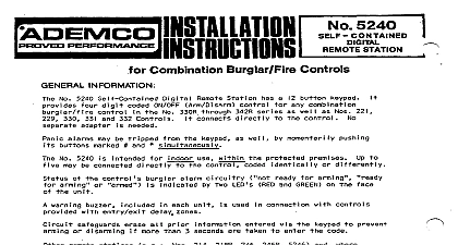
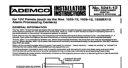
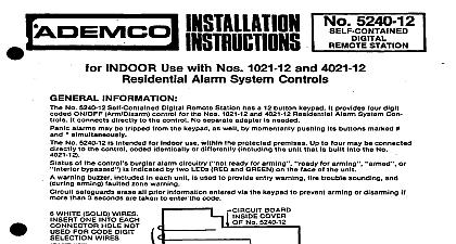
Ademco - 5241 Self-Contained Digital Remote Station

File Preview
Click below to download for free
Click below to download for free
File Data
| Name | ademco-5241-self-contained-digital-remote-station-1698420735.pdf |
|---|---|
| Type | |
| Size | 1.17 MB |
| Downloads |
Text Preview
MISTALL ATIM 5241 STATION Alarm Processing Centers Nos 1023,1024,1025,1026 Series INFORMATJON NO 5241 Setf Contained Digital Remote Station has 8 12 button keypad lt prowides four digit coded ON OFF control for Alarm Processing Centers in the Nos 1023,1024.1025 to the Control No separate adapter is needed alarms may be tripped from the keypad by momentarily pushing its buttons marked 8nd l 8Imuttaneously if desired from panic emergency devices momentary or lockin9 type boated elsewhere in tfm protected No 5241 is intended for Indoor use within When the No 5241 Is used the keyswitch normelly connected directly may NOT be used Of the control burglar alarm circuitry ready for arming LED RED and GREEN on the face of the unit warning buzzer included in each unit is used in conjunclion with the control entry exit delay zone safeguards erase all prior information entered via the keypad 10 prevent arming or disarmmg if more than 3 are taken to enter the code protected premises No more than one may be connected to the the panel for ONrOFF eon for arming or 1026 Series lt oonnects indicated by WHITE SOLID WIRES FOR CODE DIGIT WIRES DIGIT WIRES CONDUCTORS 5 2 4 9 HAS PROGRAMMED EXAMPLE SHOWN PIN CONNECTOR Bend eech end as shown before connector 1 CODE PROGRAMMING AND WIRING Select 8 four digit erm disarm value is not 8llowed i e no two digits can have the same value e g 2 2 3 7.2 3 7 2 elc cannot used for the No 5241 Remofe Station Within this four digit code repeat Of a PrCQmm the No 5241 for its assigned code 8s follows Note the following example the No 5241 is being RtmOw code S 24 9 unit 1 and position it so that the circuit board within the cover appears 8s shown in Observe the Dlglt Selection Wires the four 4 inch solid conductor wires at the left side of the cira it The colors are BROWN RED ORANGE and YELLOW Observe 10 pln connector below the right edge of the PC board lts holes are associated with digit M of 0 through 9 as indicated in Diagram 1 Note that the holes 8re not numbered sequentially Slmpty the BROWN wire In the connector hole which responds the numerical vkue for the first dlglt in Diagram l programmed ex8mple To insure good contact bend the end of each wire 8s shown in Diagram 1 before inserting it in the Slmllerly the RED ORANGE 8nd YELU W wlre8 In the holes for the 2nd 3rd and 4th dlgb and 9 in Diagmrn l progr8mmed erample Insert one of the six WHlTE wlre8 Into eech remaining connector hole and dress all wires neatly down the PC board Replace the unit cover until ready to mount in its selected location Mount the No 5241 In the desired 8nd run wiring between it and the control as shown in Diagram 2 wiring distance should not exceed 400 ft Do not connect The No 5241 Is Intended the control until Step 6 the No 217 Flush Mount Box Is WITHIN the protected premis8s Concealed wiring may enter via a large square hole in the base of unit Breakaway knockouts are provided in the base for exposed wiring wiring flush mounting surface mounting Where the Alarm Processing Center Is to be used In a Cabinet which has 8 sufteble cutout its cover No 8208 the No 5241 may be flush mounted directly on the Alarm Processing Center cover cabinet door between front and rear portions of the No 5241 and secure with 2 screws A switch for PANIC RESET is required momentary it the No 5241 panic feature is to be used Sug switches may be cabinet mounted No 2174 70 flat key No 4073 70 round key No 5073 70 higher pick resistant or simply a pushbutton such 8s the No 8064 may be used If a pushbutton be located within the Alarm Processing CenIer or in some other location where it is not in view the switch and run wiring from it to the control panel see Diagram 2 but do not connect the wires to the until Step 6 The No 524 1 panic latching feature permits on locking momentary closure panic switches as the No 219 to be connected used Any number of locking andor non locking devices may be connected in parallel Run wiring from them the control panel see Diagram 2 but do not connect to the control until Step 6 to 400 feet of 22 wire total may be used for the PANIC RESET and panic emergency switch wiring the Alarm Processing Center ordinarily only locking type devices may used it Disconnect control battery and AC power Connect wiring the control as shown Diagram 2 Note that panic emergency connections depending on whether momentary contact non or locking type devices are used ff SILENT PANIC alarm is desired connection may be made to a digital communicator Connect JI leads on terminal 8 pl the control in Diagram 2 Instead to Ihe positive by voltage 6VDC ter of a non delay channel ot the communicator not powered from the same source the control also connect a jumper between terminal 20 of the control and the negative Wiggering by terminal of the communicator not desired do not connect its VIOLET lead the communicator lf the No 5241 panic alarm Reconnect control s battery and AC power or lb26 DESIRED F NIC ALARM NOT CONNECT VIOLET SILENT PANIC WIRING 5241 PANIC RESET N 0 5241 COLORS ALARM US PANIC INPUT ADDITIONS LOCKING TYPE N WIRES No 295,4 COND plus No 269 or 2 No 295 extrawires BLACK BLUE NOTE V STATUS em STATION BUZZER SPLICE GREEN LEAD ITS OWN BLACK LEAD OMIT THIS CONNECTION WIRING RUNS TO NO 5241 4wFT FT TOTALDUT TO PANIC RESET SW ADD PANIC DEVICES BACK WITH GAGE WIRE WAY 2 FIELD CONNECTIONS AND OPERATION No 5241 will indicate the system status via its GREEN and RED LED as follows LIT STATUS Protective Circuit s Not Ready lor Arming Protective Circuits Ready for Arming fReadv for Alarm or Disannina Arm and disarm system at the No 5241 as follows and check the response of each station LED successfully enter the next disarm arm code Exception The 5 second wait can be eliminated by at least 5 seconds between successive attempts at arming or disarming with the No 524 1 or it may not be any digit not used in the 4 digit code and then the code the 4 digit code is being entered i more than 3 seconds are taken to enter the entire arm disarm me if the code digits are not entered correctly all prior entered information may be erased thus requiring code lo be started anew


