Ademco - 5800GDO Wireless Relay Module

File Preview
Click below to download for free
Click below to download for free
File Data
| Name | ademco-5800gdo-wireless-relay-module-7401359628.pdf |
|---|---|
| Type | |
| Size | 687.41 KB |
| Downloads |
Text Preview
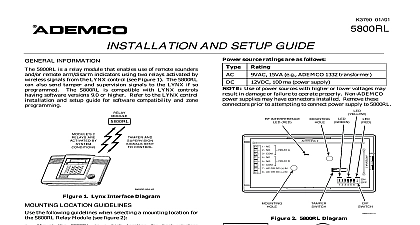
AND SETUP GUIDE 11 01 INFORMATION 5800GDO is a wireless receiver module that enables use of up to eight wireless transmitters to operate a door opener The 5800GDO may be used with the Wireless Transmitters When the 5804WATCH is used in with the 5800GDO it has a limited range Therefore use the 5804WATCH in close proximity to the garage door EX use in lieu of garage door keypad AND SETUP the following guidelines when selecting a mounting for the 5800GDO Garage Door Module Mount the 5800GDO in a high location for best reception Do not mount the 5800GDO on or near metal This decreases range and or blocks wireless The 5800GDO must be located at least 10 feet from remote keypads to avoid interference from the in those units To avoid voltage loss that occurs on long power lines external power supply unit should be mounted close proximity to the 5800GDO Before permanently mounting perform the setup procedure described in Setting Up the 5800GDO section Remove the 5800GDO cover a small screwdriver insert screwdriver tip in slot top of cover to remove Using the GDO base as a drill template position in desired location and drill two pilot holes See 1 for mounting hole location Attach the GDO base using the fasteners supplied Connect garage door opener switching wire to GDO 3 COM and terminal 1 NC or 2 NO as by the garage door opener Refer to garage if it operates with a NC or NO switch manufacturer Connect power wiring to the 5800GDO terminals Figure 1 5800GDO can be powered from either a 12VDC or external power source Rating 15VA ADEMCO 1332 100 ma 4 and 5 4 and 5 Use of power sources with higher or lower may result in damage or failure to operate Position the wiring in the exit slot and reinstall the cover on the base INTERFERENCE RED 2 NC NO COM AC OR DC IN AC OR DC IN 2 3 4 5 6 1 Connection Diagram UP THE 5800GDO Operation Yellow Red and Green LEDs located above the DIP and the RF interference LED located between the mounting holes are described below Upon Relay state OFF Reset State NC contact connected to ON Set State NO contact connects to COM relay state momentarily changes when an enrolled is pressed When power is applied the relay is to the reset state Key enrollment erase indicator Used to status during Enrolling RF Transmitters and All RF Transmitters procedures on lighted when power is applied Flickering RF is being processed when RF activity is present DIP Switch operation of the 5800 GDO requires all DIP switches be the OFF position switch 1 Enables the Erasing All RF Transmitters Mode to Erasing All RF Transmitters Section switch 2 Enables the Enrolling RF Transmitters Mode to Enrolling RF Transmitters Section switch 3 Used during Enrolling RF Transmitters Mode to Enrolling RF Transmitters section switch 4 6 Used during Erasing All RF Transmitters RF TRANSMITTERS To exit the Enrolling RF Transmitters Mode at any set DIP switch 2 to the OFF position 5800GDO will Unless otherwise noted exit the Enrolling RF Transmitters if each step is not accomplished within one of the other during the enrollment procedure excessive RF is noted as indicated by the RF Indicator LED it is advised that be exited until free of RF interference will prevent inadvertent enrollment of an wireless transmitter device Set all DIP switches to the OFF position Place DIP switch 2 in the ON position Disconnect reconnect power to the 5800GDO after power is applied the following will The green LED will turn on and remain on the EEPROM is not full the red LED will flash on off once for each transmitter that can still be and then lights steady the EEPROM is full 8 wireless keys enrolled the LED will remain on indicating that no more can be enrolled enrolling An encrypted 5804E and press and hold all 4 buttons at same time Verify the red LED turns off A bi directional encrypted press and hold the B C D buttons the same time Verify the red LED turns off press the button to be enrolled twice the red LED turns off A non encrypted Place DIP switch 3 in the ON position Press and release the button that will be used to the garage door Verify the red LED flashes times If an incorrect wireless transmitter is enrolled DIP switch 3 to OFF and repeat the enrollment from step 4 To add an additional button on the same key repeat Place DIP switch 3 in the OFF position to accept the Repeat steps 4 through 8 to enroll additional When all devices are enrolled place DIP switch 2 in 6 for that button enrolled transmitters OFF position ALL RF TRANSMITTERS To exit this procedure at any time set DIP switch 1 the OFF position and wait 5 seconds before procedure Unless otherwise noted 5800GDO will exit the Erasing All RF Transmitters if each step is not accomplished within one of the other Place DIP switch 1 in the ON position Disconnect reconnect power to the 5800GDO after power is applied the following will The green LED will turn on and remain on the EEPROM is not full the red LED will flash on off once for each transmitter that can still be and then lights steady the EEPROM is full 8 wireless keys enrolled the LED remain on indicating no more transmitters be enrolled Place all DIP switches opposite to their current within one minute of applying power in step All DIP switches must be switched opposite to current position within 5 seconds of each other avoid exiting this procedure Return all DIP switches to their original positions verify the red LED turns off the red LED turns off all transmitters have erased W x 4 15 16 H x 1 1 16 D x 125mm x 27mm OR 15VA use ADEMCO 1332 or equivalent relay with choice of normally open or normally operation Ratings 2 Amps at 28VDC Temperature 122 0 50 COMMUNICATIONS COMMISSION FCC STATEMENT equipment has been tested to FCC requirements and has been found acceptable for use The FCC requires the following for your information using an indoor antenna have a quality outdoor antenna installed equipment generates and uses radio frequency energy and if not installed and used properly that is in strict accordance the manufacturer instructions may cause interference to radio and television reception It has been type tested and found comply with the limits for a Class B computing device in accordance with the specifications in Part 15 of FCC Rules which designed to provide reasonable protection against such interference in a residential installation However there is no that interference will not occur in a particular installation If this equipment does cause interference to radio or tel