Ademco - 5800RP Wireless Repeater
File Preview
Click below to download for free
Click below to download for free
File Data
| Name | ademco-5800rp-wireless-repeater-0563198274.pdf |
|---|---|
| Type | |
| Size | 641.41 KB |
| Downloads |
Text Preview
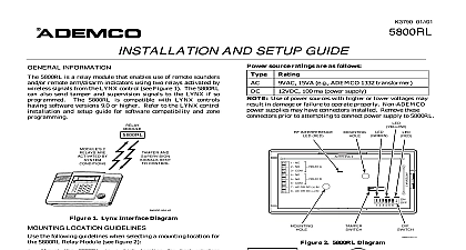
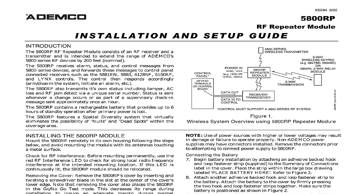
cid 44 cid 49 cid 54 cid 55 cid 36 cid 47 cid 47 cid 36 cid 55 cid 44 cid 50 cid 49 cid 3 cid 36 cid 49 cid 39 cid 3 cid 54 cid 40 cid 55 cid 56 cid 51 cid 3 cid 42 cid 56 cid 44 cid 39 cid 40 5800RP RF Repeater Module consists of an RF receiver and a and is intended to extend the range of ADEMCO series RF devices by 200 feet nominal 5800RP receives alarm status and control messages from series devices and forwards these messages to control panel receivers such as the 5881EN 5883 6128RF 6150RF LYNX controls The control then responds accordingly the system initiate an alarm etc 5800RP also transmits it own status including tamper AC and RF jam detect via a unique serial number Status is sent a change occurs or as part of a supervisory check in sent approximately once an hour 5800RP contains a rechargeable battery that provides up to 6 of standby operation after primary power is lost 5800RP features a Spatial Diversity system that virtually the possibility of Nulls and Dead Spots within the area THE 5800RP MODULE the 5800RP remotely in its own housing following the steps and avoid mounting the module with its antennas touching metal surface for RF Interference Before mounting permanently use the RF Interference LED to check for strong local radio frequency at the intended mounting location If this LED is lit the 5800RP module should be relocated the Cover Remove the 5800RP cover by inserting and a screwdriver blade in the slot at the center of the cover edge Note that removing the cover also places the 5800RP the Go No Go Test mode This decreases its range during to an adequate margin during normal the Module For concealed wiring route power wires through the opening at the rear of the base before mounting surface wiring entry a thin breakaway area is provided the base right edge Mount the module in the selected location For greatest use all four mounting holes two keyslot holes and round holes in the plastic base Install each antenna in the respective right hand terminal of two terminal blocks at the upper edge of the 5800RP board and tighten the screws to secure them Affix the Summary of Connections label to the inside of the cover Make sure the arrows and large sign on label line up with the corresponding posts in the cover If applicable set the Site ID by referring to the Setting the ID section on the next page the Power Supply 5800RP can be powered from either an AC or DC external source connected to terminals 1 and 2 see figure 2 source ratings are as follows 15VA e g ADEMCO 1332 100 ma Connect the power supply to the 5800RP terminals Refer to 2 These terminals are not polarized The leads from supplies may be connected to either terminal 6 02 CONTROL IN 15VA 1332 OR 100mA OUT IN TO SERIES TRANSMITTER KEYPAD 5827BD 5804BD 2 WAY RELAY MUST SUPPORT A 5800 SERIES RF SYSTEM 1 System Overview using 5800RP Repeater Module Use of power sources with higher or lower voltages may result damage or failure to operate properly Non ADEMCO power may have connectors installed Remove the connectors prior attempting to connect power supply to 5800RP the Battery Begin battery installation by attaching an adhesive backed hook loop fastener strip supplied to the Summary of Connections in the cover Place the strip within the large box drawing BATTERY HERE Refer to Figure 2 Attach another adhesive backed hook and loop fastener strip to battery Attach the battery to the cover by firmly pressing two hook and loop fastener strips together Make sure the is positioned as shown in Figure 2 Plug the battery cable into the battery connector on the 5800RP Refer to Figure 2 NOTE The battery must be allowed to charge at 12 hours in order to reach its full capacity Replace the cover on the 5800RP being careful not to pinch the wires between the cover and case or any PCB components IN BOARD INTERFERENCE INDICATOR RED WHEN SITE ID YEL RED SWITCH 3 4 5 6 7 8 SUMMARY CONNECTIONS HERE COVER 2 Repeater Module Layout and Connections FOR THE SITE ID ADEMCO wireless devices e g 5827 5804BD use a house ID to help avoid communication conflicts with installations The 5800RP automatically passes all house information to the appropriate receiver newer ADEMCO wireless devices such as the 5883 and 5839 use a ID instead of a House ID The Site ID is a unique serial number built into each 5883 and must be entered into each device that uses it The ID provides many more combinations than a House ID and is less likely to have conflicts with nearby installations using the 5800RP with wireless devices that use a Site ID the steps below to enter a permanent copy of the Site ID in 5800RP This procedure assumes that all such devices have successfully set up and tested with the 5883 although they not yet be mounted in their final locations Put the control and the 5883 in the Go No Go Test mode Remove the 5800RP cover by inserting and twisting a blade in the slot at the center of the cover lower Note that removing the cover also places the 5800RP in Go No Go Test mode This decreases its range during to insure an adequate margin during normal Temporarily disconnect the power supply and battery from 5800RP Refer to Figure 2 Place DIP switch 1 in the ON position Reconnect the power supply to the 5800RP Observe that the LED on the 5800RP turns on and remains on This that the 5800RP is ready to set the Site ID Push and release the tamper switch on the 5800RP This a set up request message to be sent to the 5883 Observe that the red LED turns off indicating that the Site has been saved in the 5800RP If not repeat the previous until it does If the tamper switch is not pushed for 1 minute or if switch 1 is turned off the red LED turns off This the 5800RP will no longer accept the Site ID Place DIP switch 1 in the OFF position Replace the cover on the 5800RP Take the control out of the Go No Go Test mode If needed locate the other wireless devices in their final Test all wireless devices WHEN ID BE OFF BE OFF NON UL BE ON UL 8 USED BE OFF 3 5800RP DIP Switch FUNCTIONS Interference Upon on lighted when power AC or battery is Flickering indicates RF is being processed off Blinks an RF is being sent by the 5800RP off Turns on lighted when setting Site See the Setting the Site ID section for details when RF activity is present 2 AND OPERATIONAL NOTES Installations switch 2 must be OFF during normal operation Set DIP switch 2 to OFF If module supervision is desired assign the 5800RP to a zone for check in low battery AC loss and RF jam messages enroll its serial number When prompted toggle the tamper to enroll the serial number The yellow LED should blink when messages are sent the zone as follows Type 24 hour aux Type supervised RF The 5800RP reports AC loss and RF jam conditions as status which is also displayed on the control