Ademco - 5804BD Bi-Directional Wireless Key Installation Manual

File Preview
Click below to download for free
Click below to download for free
File Data
| Name | ademco-5804bd-bi-directional-wireless-key-installation-manual-9276108354.pdf |
|---|---|
| Type | |
| Size | 982.68 KB |
| Downloads |
Text Preview
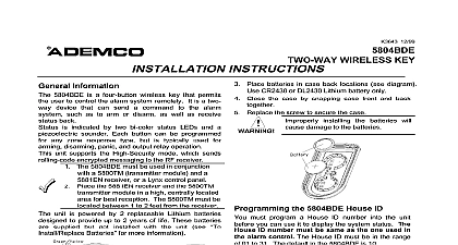
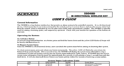
Several of you have written us to ask that we reconsider this decision We have Tech Man Subscriber apologizes for any misunderstanding that has arisen due to our recent to have our technical information removed from the Tech Man web site You appreciate that one of our key concerns is to provide installing security dealers with and accurate information on our products and we were concerned about the data to the Tech Man web site For obvious reasons we also do not wish unauthorized to have access to information on installing and configuring ADEMCO These concerns were what prompted us to ask Tech Man to stop posting installation instructions and user manuals will not require Tech Man to remove the ADEMCO data ADEMCO however is responsible for the operation and maintenance of this site thus we cannot guarantee timeliness or accuracy of the information posted on the Tech Man web site data about our products You may request a PIN number for access to the Technical Support web site and FAXBACK system you need assistance on troubleshooting or if you have other technical questions our products not addressed in the information posted at our web site please contact Technical Support at 800 645 7492 ADEMCO web site is located at www ademco com and contains accurate you for understanding Lustig 04 97 WIRELESS KEY INSTRUCTIONS Information 5804BD is a four button wireless key that permits an alarm system to be controlled remotely It is a two device which means that it can send a command to the alarm system such as to arm or disarm as well receive status back from the control Status is indicated by two bi color status LEDs and a piezoelectric Each button can be programmed for any zone response type by using the alarm system mode Typical use is for arming disarming panic and output relay operation 5804BD must be used in conjunction with a 5800TM Transmitter Module and 5881 RF Receiver unit is powered by 2 replaceable Lithium batteries designed to provide up to 2 years of life see Batteries for more information Assignments Button A Loop 3 Button B Loop 2 Button C Loop 4 Button D Loop 1 Remove or Insert the Unit from Belt Clip Place the 5881 receiver and 5800TM transmitter module in high centrally located area for reception The 5800TM must be located between and 2 feet from the receiver Install Replace Batteries Remove the screw from the back case Remove case back by using the blade of a small screwdriver to pry Place batteries in case back locations see diagram Use CR2430 or Close the case by snapping case front and back together Replace the screw to secure the case Lithium battery only installing the batteries will cause damage the batteries WARNING the 5804BD House ID need to program a House ID number into the unit before you can to use it to display the system status House ID number must be same as the one used in the alarm control The House ID must be in the of 01 to 31 The default in the 5804BD is 10 Enter a House ID Enter House ID mode by pressing the and buttons at the same time until the Red and Green LEDs flashing Enter the House ID number by using the button to enter the 10 digit and the button to enter the 1 Note If the entry is out of range greater than 31 the unit will generate a long beep and discard the Accept the entry by pressing the button The unit displays the stored number by flashing the left LED for the 10 digit and flashing the right LED for the digit for example for House ID 21 the left LED will flash twice the right LED will flash once The unit will then exit the House ID mode a beep will be heard To enter House ID 17 into the unit HID mode A B C buttons LEDs flash HID 17 Press release A button press release button 7 times accept entry press button will be shown by LEDs Then HID mode View the House ID Enter House ID mode as described in step 1 above Depress the button to view The unit displays the stored number as described in step 4 above The unit will then exit House ID mode a beep will be heard a House ID in the Alarm Control On Vista 40 50 50P 100 and up use Device Programming mode to enable the RF receiver and enter the House number On Via 30 Vista 20 and below go to field 24 and enter the House ID number the Buttons 5804BD is assigned a unique serial number during manufacture Each button on the unit also has a unique that must be programmed into the alarm control during installation Assign each button to an individual zone and program the Input Type as Type RF entry of in the control Zone Programming mode input the serial number by one of the following methods enter the serial number manually through the keypad serial number through VLINK downloading software the serial number of the device into the system as described in the alarm control Installation Instructions sure to include the loop number of each button during programming see loop assignments on previous page C you choose not to use the button you must do the following to avoid a condition when the button is pressed Assign this button to a zone see a Button to a Zone After the serial number has been programmed re enter Zone Programming for that zone At the Type prompt enter 00 and press On Via 30 controls and below the system will ask whether you want to permanently delete that zone Enter 0 No This will cause the system to retain the serial number but render the button inactive On Vista 40 and above continue to press until you see the zone No prompt again At this point Press and Then press 99 to exit program mode 2 Button a button assigned to a zone type 20 Arm Stay 21 Arm Away and 22 Disarm you must do the following Vista 40 50 50P 100 and up must assign a user to the button in order for it to operate assign a user number to the Arm Disarm button Enter 4 digit User Code 8 User 4 digit new User Via 30 Vista 20 and below do not have to assign a user to the button The panel will the zone number as the user number to the central station Answer Yes or No on the Report question Answer Yes on the Button question Enter the zone assigned to the Arm Disarm button Keypad shows the summary of user information on its display Test Arm Disarm button to make sure it operates correctly the Buttons Activate a Button activate programmed function on a button press and hold the button down until the yellow LED flashes 2 beeps will heard and then release it Request System Status the 5804BD is a two way device users can check the system status before arming or disarming their system To system status press and release any button momentarily The yellow LED will flash after you release the button beep will be heard After a second or two the 5804BD will display the system status information using a combination LED and sounder activity see the System Status Indications Table below If 5804BD does not receive system status from the panel for approximately five seconds it will generate a long 1 second beep and shut itself down It also shut itself down if there is no button activity within five seconds of receiving a status update device may not receive the system status properly if it within a few feet of the 5881 RF receiver right Green Status Indications Table Condition Steady Steady Steady Flashing Beeps Beeps Beep Status Away or Maximum Stay or Instant Alarm in progress Burglary Alarm in progress Memory Ready to Arm Not Ready to Arm RF transmission


