Ademco - 5807 Smoke Detector With Wireless Transmitter

File Preview
Click below to download for free
Click below to download for free
File Data
| Name | ademco-5807-smoke-detector-with-wireless-transmitter-6907843125.pdf |
|---|---|
| Type | |
| Size | 926.16 KB |
| Downloads |
Text Preview
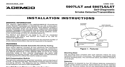
Several of you have written us to ask that we reconsider this decision We have Tech Man Subscriber apologizes for any misunderstanding that has arisen due to our recent to have our technical information removed from the Tech Man web site You appreciate that one of our key concerns is to provide installing security dealers with and accurate information on our products and we were concerned about the data to the Tech Man web site For obvious reasons we also do not wish unauthorized to have access to information on installing and configuring ADEMCO These concerns were what prompted us to ask Tech Man to stop posting installation instructions and user manuals will not require Tech Man to remove the ADEMCO data ADEMCO however is responsible for the operation and maintenance of this site thus we cannot guarantee timeliness or accuracy of the information posted on the Tech Man web site data about our products You may request a PIN number for access to the Technical Support web site and FAXBACK system you need assistance on troubleshooting or if you have other technical questions our products not addressed in the information posted at our web site please contact Technical Support at 800 645 7492 ADEMCO web site is located at www ademco com and contains accurate you for understanding Lustig 4 94 DETECTOR BUILT IN TRANSMITTER INSTRUCTIONS INFORMATION Ademco No 5807 Photoelectric Smoke Detector Transmitter is intended for with wireless alarm systems that support 5800 series devices and contains a transmitter which can send alarm supervisory and battery condition to the system receiver control unit Refer to the wireless system for the maximum number of transmitters that can be supported The smoke detector is powered by two 9 volt batteries and will sound built in horn when smoke reaches the detector and the LED indicator will light A message will also be sent to the wireless control and the smoke ID number will be displayed at the console The alarm message will be every 4 seconds until the smoke condition has cleared and the has reset After the horn has stopped a Restore message will be to the control and it will then be possible to clear the ID number from display During normal or low battery conditions the LED indicator will flash once every 7 seconds Battery The detector indicates a low battery condition by emitting a beep once every 15 seconds A low battery message will be sent to the control upon any transmission following the first battery beep with the detector ID displayed at the console The battery should be replaced within 7 days the low battery signals Note that the control system must cid 210 learn cid 211 the smoke detector cid 213 s ID installation of the system The control should be programmed to cid 210 learn cid 211 5807 as an cid 210 RF cid 211 type unit i e supervised RF See the PROGRAMMING in this instruction book and the control unit cid 213 s Installation Instructions for details ON ALARM R E S S TAB 1 Smoke Detector BUTTON DE V I CE MANUFACTURI NG CO DIVISION OF PITTWAY CORPORATION Eileen Way Syosset New York 11791 4 94 1992 Pittway Corporation PROCEDURE the detector mounting bracket by pressing the tab marked PRESS in detector base see Fig 1 for location of the tab Note the manner in which bracket was attached to the detector base then put the mounting bracket temporarily The mounting bracket also serves as the battery compartment Installation The detector battery compartment cover mounting bracket should have been as previously indicated See Figure 2 two fresh Duracell MN 1604 9 volt alkaline batteries in their correct in the detector battery compartment Be sure to observe correct and do not force the batteries into the compartment The detector indicator should flash once every 7 seconds indicating normal operation the batteries are not installed correctly the smoke detector will not function the unit appears not to be sending a signal during any of the tests that check for correct battery installation BATTERIES ARE REMOVED AND RE INSERTED FOR ANY REASON re inserting the batteries momentarily bridge the smoke detector contacts with a metal tool or wait 90 seconds VOLT ALKALINE SCREWDRIVER HERE AND TWIST RELEASE COVER VOLT ALKALINE 2 View of Smoke Detector mounting bracket removed I f the detector cid 213 s ID has not been programmed into the system i e this is initial detector installation refer to the PROGRAMMING section below and the ID cid 210 learning cid 211 procedure before mounting or testing the detector control system must cid 210 learn cid 211 the smoke detector cid 213 s ID during installation of the The control should be programmed to learn the 5807 as an cid 210 RF cid 211 type i e supervised RF gain access to the special shorting contacts provided for programming insert the blade of a small screwdriver into the opening in the detector see Fig 2 for location and twist This will release the main cover which will swing away providing access to the interior of the detector as shown in 3 With the control in the programming mode short the two contacts in the shown in Figure 3 with a small screwdriver to send a FAULT and then thescrewdriver to send a RESTORE See the control unit cid 213 s installation for further details When this procedure has been completed swing down firmly to secure 2 REGARDING SMOKE DETECTOR INSTALLATION CONTACTS SCREWDRIVER SEND 3 view of Detector The Smoke Detector determine the best location for the smoke detector one that provides wireless transmission paths AND proper smoke detector protection See and LOCATIONS FOR SMOKE DETECTORS on a following page A RF transmission path must be established from the proposed mounting before permanently installing the detector To check perform the test in Transmission Path Test Mounting Locations should be located as close to the center of the ceiling as possible If is not practical detectors may be located on the ceiling up to 4 inches 10cm the ceiling wall junction Do not install near forced air heating or air ducts outlets or returns For sloped gabled or high peaked detectors must be mounted between 4 and 6 inches 10 and 15cm from highest point in the ceiling may also be wall mounted if permitted by local and state codes Check your local Fire Department about code requirements Wall mounted should be located 4 inches 10 cm from the ceiling In mobile battery operated detectors are not generally installed by the Mount detectors ONLY on an interior wall cm IN IN AIR IN cm ARE TO THE EDGE OF DETECTOR IN cm WALL 3 Transmission Path Test good RF transmission path must be established from the proposed mounting before permanently installing the smoke detector To determine that is good signal reception from the proposed location do the following Activate the wireless system test mode Depress and hold the smoke detector TEST button for at least 45 seconds 15 seconds the detector horn will start to sound and the unit will to transmit alarm signals about once every 4 seconds The wireless system console will emit at least 3 tones each time an alarm is received and will display the transmitting detector ID When the above has occurred release the button Within 10 seconds the horn will stop About 1 second later the ID number will clear from console display the console does not respond as noted move the det