Ademco - 5816TEMP Low Temperature Transmitter

File Preview
Click below to download for free
Click below to download for free
File Data
| Name | ademco-5816temp-low-temperature-transmitter-9581072634.pdf |
|---|---|
| Type | |
| Size | 954.91 KB |
| Downloads |
Text Preview
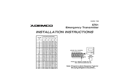
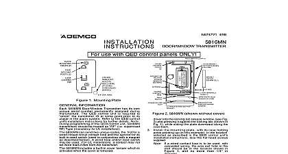
GENERAL THE NUMBER 5 95 5816TEMP TEMPERATURE TRANSMITTER INSTRUCTIONS No 5816TEMP Low Temperature Transmitter contains a low temperature detector that transmits a alarm or trouble depending on the installer programming entry to a 5800 wireless receiver that is to a control panel The message is sent when the Temperature Sensor thermostat temperature 45 cid 176 F 5 cid 176 F 4 cid 176 C 3 cid 176 C The device resets after a temperature rise of about 9 cid 176 F 5 cid 176 C for minutes At that time a restore message is sent to the receiver and the control panel 5816TEMP is permanently assigned its own serial number The control panel is required to learn the serial number prior to the transmitter usage to the control panel Installation Instructions for general information on the learning procedure information given herein is specific to the 5816TEMP Place a battery in the battery holder as described later in BATTERY INSTALLATION REPLACEMENT as shown in Diagram 2 Observe polarity While in the learning serial number program mode as described in the control panel instructions the temperature sensor by bringing a magnet close parallel to the sensor and removing it do this to send two consecutive transmissions This is depicted in Diagram 2 Exploded View The polarity of the magnet must be correct if the device does not appear to be transmitting reverse magnet direction proper orientation of the unit in relation to its wall mounting plate and the loop wiring read all of this section installing the unit within close proximity to iron steel and magnetic materials will affect the activation Do not mount the unit within 1 ft of these types of materials description that follows assumes that the unit will be mounted as shown in the diagrams The unit may be installed in any direction as long as the relationship of the unit to its mounting plate is maintained two holes are provided in the unit that would permit mounting directly to a surface holes in 2 it is recommended that the mounting plate be used as described below for ease in removing the for servicing should it become necessary mounting the transmitter permanently conduct Go No Go tests see control instructions to verify signal strength and reorient or relocate the transmitter if necessary When a satisfactory location is remove the battery and proceed with installation Disengage the supplied wall mounting plate from the unit by inserting the blade of a small screwdriver the locking tab release window Diag 2 and pressing it against the locking tab Diag 1 while sliding plate downward along the case back the mounting plate with its case holding posts pointing up in the location selected as described in control panel Installation Instructions Use the screws supplied The word TOP is molded along the edge of the plate Remove the transmitter cover by inserting the flat blade of a small screwdriver into the closed pry off at the end of the unit farthest from the cover decorative ribs and twisting the blade Attach the case back to the mounting plate by sliding the keyhole slots in the case back down onto the plate case holding posts the battery as described in BATTERY INSTALLATION procedure on the next page Replace unit cover by engaging the case holding posts along the edge and snap shut 2 2 LOCKING TAB A 2 TEXT STRIP PRY OFF POINT LEARNING BRING PARALLEL TO AND REMOVE THIS TWICE 2 TAB WINDOW 1 MOUNTING PLATE 2 No 5816TEMP Shown With Cover Removed Remove the transmitter cover if not already off as described in Mounting Step 3 Observe polarity and insert the battery provided into the battery holder see Diagram 2 not bend the antenna Replace only with Duracell DL 123A Sanyo CR123A Panasonic CR123A or Ademco 466 Risk of fire explosion and burns Do not recharge disassemble heat above 212 cid 176 F 100 cid 176 C or Dispose of used batteries promptly Keep away from children To replace the cover engage the case holding posts along one edge and snap shut x 3 1 2 H x 1 3 16 D 40mm x 89mm x 30mm Lithium Duracell DL123A Sanyo CR123A Panasonic CR123A or Ademco 466 thermostat activation temperature is 45 cid 176 F 5 cid 176 F 4 cid 176 C 3 cid 176 C The device resets after a temperature of about 9 cid 176 F 5 cid 176 C for 5 minutes The device may be reset manually using a magnet after a 4 cid 176 F 2 cid 176 C rise magnet polarity must be aligned THE INSTALLER maintenance and inspection at least annually by the installer and frequent testing by the user are vital to continuous operation of any alarm system installer should assume the responsibility of developing and offering a regular maintenance program to the user as well as the user with the proper operation and limitations of the alarm system and its component parts must be included for a specific program of frequent testing at least weekly to insure the system proper at all times TO THE INSTALLATION INSTRUCTIONS FOR THE RECEIVER CONTROL WITH WHICH THIS DEVICE IS USED DETAILS ON LIMITATIONS OF THE ENTIRE ALARM SYSTEM LIMITED WARRANTY Device Manufacturing Company a Division of Pittway Corporation and its divisions subsidiaries and affiliates Seller Eileen Way Syosset New York 11791 warrants its products to be in conformance with its own plans and specifications and be free from defects in materials and workmanship under normal use and service for 18 months from the date stamp con trol the product or for products not having an Ademco date stamp for 12 months from date of original purchase unless the instructions or catalog sets forth a shorter period in which case the shorter period shall apply Seller obligation shall limited to repairing or replacing at its option free of charge for materials or labor any product which is proved not in with Seller specifications or proves defective in materials or workmanship under normal use and service Seller have no obligation un der this Limited Warranty or otherwise if the product is altered or improperly repaired or serviced by other than Ademco factory service For warranty service return product transportation prepaid to Ademco Factory 165 Eileen Way Syosset New York 11791 ARE NO WARRANTIES EXPRESS OR IMPLIED OF MERCHANTABILITY OR FITNESS FOR A PARTICULAR OR OTHERWISE WHICH EXTEND BEYOND THE DESCRIPTION ON THE FACE HEREOF IN NO CASE SHALL BE LIABLE TO ANYONE FOR ANY CONSEQUENTIAL OR INCIDENTAL DAMAGES FOR BREACH OF THIS OR OTHER WARRANTY EXPRESS OR IMPLIED OR UPON ANY OTHER BASIS OF LIABILITY WHATSOEVER EVEN IF LOSS OR DAMAGE IS CAUSED BY THE SELLER OWN NEGLIGENCE OR FAULT does not represent that the products it sells may not be compromised or circumvented that the products will prevent any injury or property loss by burglary robbery fire or otherwise or that the products will in all cases provide adequate or pro tection Customer understands that a properly installed and maintained alarm may only reduce the risk of a bur robbery fire or other events occurring without providing an alarm but it is not insurance or a guarantee that such will not or that there will be no personal injury or property loss as a result CONSEQUENTLY SELLER SHALL HAVE NO FOR ANY PERSONAL INJURY PROPERTY DAMAGE OR OTHER LOSS BASED ON A CLAIM THE PRODUCT TO GIVE WARNING HOWEVER IF SELLER IS HELD LIABLE WHETHER DIRECTLY OR INDIRECTLY FOR ANY OR DAMAGE ARISING UN DER THIS LIMITED WARRANTY OR OTHERWISE REGARDLESS OF CAUSE OR ORIGIN MAXIMUM LIABILITY SHAL