Ademco - 5817 Multi-Point Universal Transmitter

File Preview
Click below to download for free
Click below to download for free
File Data
| Name | ademco-5817-multi-point-universal-transmitter-6348912750.pdf |
|---|---|
| Type | |
| Size | 615.06 KB |
| Downloads |
Text Preview
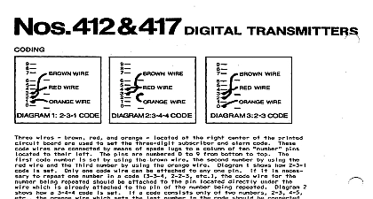
Several of you have written us to ask that we reconsider this decision We have Tech Man Subscriber apologizes for any misunderstanding that has arisen due to our recent to have our technical information removed from the Tech Man web site You appreciate that one of our key concerns is to provide installing security dealers with and accurate information on our products and we were concerned about the data to the Tech Man web site For obvious reasons we also do not wish unauthorized to have access to information on installing and configuring ADEMCO These concerns were what prompted us to ask Tech Man to stop posting installation instructions and user manuals will not require Tech Man to remove the ADEMCO data ADEMCO however is responsible for the operation and maintenance of this site thus we cannot guarantee timeliness or accuracy of the information posted on the Tech Man web site data about our products You may request a PIN number for access to the Technical Support web site and FAXBACK system you need assistance on troubleshooting or if you have other technical questions our products not addressed in the information posted at our web site please contact Technical Support at 800 645 7492 ADEMCO web site is located at www ademco com and contains accurate you for understanding Lustig LIMITED WARRANTY Device Manufacturing Company a Division of Pittway Corporation and divi sions subsidiaries and affili ates Seller 165 Eileen Way Syosset York 11791 warrants its products to be in conformance with its own plans specifications and to be free from defects in materials and workmanship normal use and service for 18 months from the date stamp control on product or for products not having an Ademco date stamp for 12 months date of original purchase un less the installa tion instructions or catalog forth a shorter period in which case the shorter period shall apply Seller shall be limited to repairing or replacing at its option free of charge materials or labor any product which is proved not in compliance with specifica tions or proves defective in materials or workmanship under use and service Seller shall have no obligation under this Limited or otherwise if the product is altered or improperly repaired or by anyone other than Ademco fac tory service For warranty service product transportation pre paid to Ademco Factory Service 165 Eileen Syosset New York 11791 ARE NO WARRANTIES EXPRESS OR OF OR FITNESS FOR A PARTICULAR PURPOSE OR WHICH EXTEND BEYOND THE DESCRIPTION ON THE HEREOF IN NO CASE SHALL SELLER BE LIABLE TO ANYONE FOR CONSEQUENTIAL OR INCIDENTAL DAMAGES FOR BREACH OF OR ANY OTHER WARRANTY EXPRESS OR IMPLIED OR UPON OTHER BASIS OF LIABILITY WHATSOEVER EVEN IF THE LOSS OR IS CAUSED BY THE SELLER OWN NEGLIGENCE OR FAULT does not represent that the products it sells may not be compromised or that the products will prevent any personal injury or property loss bur glary robbery fire or otherwise or that the products will in all cases adequate warning or pro tection Customer understands that a properly and maintained alarm may only reduce the risk of a bur glary robbery or other events occurring without providing an alarm but it is not insurance a guarantee that such will not occur or that there will be no personal injury or loss as a result CONSEQUENTLY SELLER SHALL HAVE NO FOR ANY PERSONAL INJURY PROPERTY DAMAGE OR LOSS BASED ON A CLAIM THE PRODUCT FAILED TO GIVE HOWEVER IF SELLER IS HELD LI ABLE WHETHER DIRECTLY INDIRECTLY FOR ANY LOSS OR DAMAGE ARISING UNDER THIS WARRANTY OR OTHERWISE REGARDLESS OF CAUSE OR SELLER MAXIMUM LIABILITY SHALL NOT IN ANY CASE THE PURCHASE PRICE OF THE PRODUCT WHICH SHALL BE COMPLETE AND EXCLUSIVE REMEDY AGAINST SELLER This war replaces any previous warranties and is the only warranty made by Seller this product No increase or alteration written or verbal of the obligations of Limited Warranty is authorized DEVICE MANUFACTURING COMPANY DIVISION OF PITTWAY CORPORATION Eileen Way Syosset New York 11791 3 95 1992 PITTWAY CORPORATION 3 95 5817 TRANSMITTER INSTRUCTIONS INFORMATION No 5817 Multi Point Universal Transmitter may have three contact loops connected it Each loop transmits a unique ID code to a 5800 wireless system receiver connected to system control panel The Primary Loop has several DIP switch selectable options that its connection requirements response and transmis sion characteris tics see switch setting table on next page The two Auxiliary Loops are closed circuit with a response time of 100 mSec For UL installations no contact in any of the loops be more than 3 feet from the transmitter built in cover tamper switch is activated when the cover is removed THE TRANSMITTER IDs No 5817 has its own unique identification codes permanently assigned dur ing manu It is not neces sary to program the transmitter IDs during installation Instead the unit is required to learn the transmitter IDs at some point prior to the transmitter in the alarm system control unit installation manual contains general information on the learning proce but the information given herein pertains specifically to the 5817 Place a 3V battery in the battery holder as described later in BATTERY INSTALLA and as shown in Diagram 2 Observe polarity Make sure that the DIP switch 4 positions see Diagram 2 are all OFF Set the system ready for learning the ID code of one of the 5817 loops inputs to used as described in the control instructions The 5817 should be treated as RF supervised RF Type mandatory for UL installations Proceed with learning the inputs of the loops to be used as described in the con instructions proper orientation of the unit in relation to its wall mounting plate and the loop wiring all of this section before installing the unit description that follows assumes that the unit will be mounted as shown in the dia The unit may however be installed in any direction as long as the relationship of unit to its mounting plate is maintained two holes are provided in the unit that would permit mounting directly to a sur face in Diagram 2 it is recom mended that the mounting plate be used as described for ease in removing the unit for servicing should it become necessary mounting the transmitter permanently conduct Go No Go tests see control in to verify adequate signal strength and reorient or relocate the transmitter if nec When a satisfactory location is found remove the battery and proceed with installa Remove the transmitter cover by inserting the flat blade of a small screwdriver into pry off slot at the end of the unit farthest from the cover decorative ribs and twist the blade Note The open slot at the other end of the unit cannot be used as a pry off Disengage the supplied mounting plate from the unit by inserting the blade of a screwdriver into the locking tab release window see Di agram 2 and pressing it the locking tab see Diagram 1 while sliding the plate down ward along the case Note For this application the alignment guide strip along one edge of the plate no function and may be broken away if desired concealed wiring is to be used feed the wires through the con cealed wiring entry at one corner of the plate surface wiring is mentioned in Step 5 below the mounting plate with its case holding posts point ing up in this example in location selected as described in the control unit installation instruc tions Use the head screws sup plied concealed wiring is to be used feed it through the slot in the case back but do not to the terminal block yet Surface wiring should enter via the thin breakout pro vided in the case wall Attach the case back to the mounting plate by slid ing the key hole slots in the case down onto the mounting plate hooks The locking tab will click as the case back in place Set the DIP switch after the control has learned the transmiter input IDs for the de primary loop characteristics as described in the table below