Ademco - 5818 Recessed Door Transmitter

File Preview
Click below to download for free
Click below to download for free
File Data
| Name | ademco-5818-recessed-door-transmitter-3072456981.pdf |
|---|---|
| Type | |
| Size | 603.50 KB |
| Downloads |
Text Preview
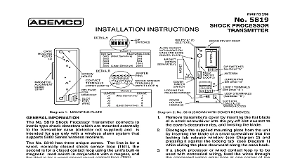
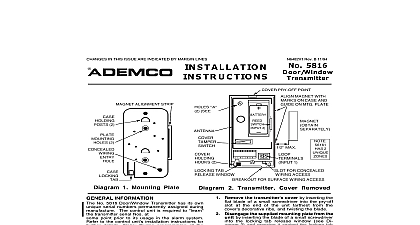
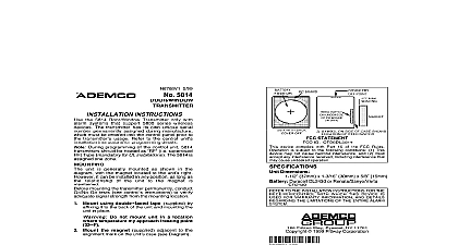
Several of you have written us to ask that we reconsider this decision We have Tech Man Subscriber apologizes for any misunderstanding that has arisen due to our recent to have our technical information removed from the Tech Man web site You appreciate that one of our key concerns is to provide installing security dealers with and accurate information on our products and we were concerned about the data to the Tech Man web site For obvious reasons we also do not wish unauthorized to have access to information on installing and configuring ADEMCO These concerns were what prompted us to ask Tech Man to stop posting installation instructions and user manuals will not require Tech Man to remove the ADEMCO data ADEMCO however is responsible for the operation and maintenance of this site thus we cannot guarantee timeliness or accuracy of the information posted on the Tech Man web site data about our products You may request a PIN number for access to the Technical Support web site and FAXBACK system you need assistance on troubleshooting or if you have other technical questions our products not addressed in the information posted at our web site please contact Technical Support at 800 645 7492 ADEMCO web site is located at www ademco com and contains accurate you for understanding Lustig I I 5 1 98 11 31 AM Page 1 5818 TRANSMITTER 4 98 INSTRUCTIONS use with QED control panels ONLY INSTALLATION TRANSMITTER INFORMATION No 5818 Recessed Transmitter is a reed magnetic contact sensor that provides protection for a door or window It intended for use only with alarm systems support QED 5800 series devices transmitter is powered by a long life battery that is easily replaceable when low battery is indicated by the control the ID Number 5818 has its own unique identification serial number permanently assigned manufacture control unit is required to the ID during installation of the system The 5818 response should be as i e Supervised RF Type for ULinstallations to the QED control unit installation for further details CONSIDERATIONS all of this and the next section before the unit Select a location for the transmitter the frame of the door never on the edge or window to be Do not use on metal frame doors or The transmitter will require a 7 8 diameter in the edge of the frame at least 5 and its magnet will need a 1 2 hole in the edge of the door or at 1 3 4 deep BUT DRILLING ANY HOLES SEE 2 BELOW AND MOUNTING ON NEXT PAGE The preferred direction of mounting is although the 5818 may be in any direction if satisfactory of its transmissions is obtained A physical barrier e g a molding strip on door or window frame should be to protect against defeat of the from outside the premises Before drilling any holes and magnet in their approximate with battery installed and unit as described under BATTERY below conduct Go No Go tests see QED instructions to verify adequate strength Reorient or relocate the if necessary Make sure that no more than a 1 2 gap be present between the faces of the and magnet cases when they installed and set When installed an alarm signal must be before a clear space of 2 is as the door or window is opened I I 5 1 98 11 31 AM Page 2 Mark the selected location for the on the frame of the door window Mark the location for the magnet on door or window directly opposite transmitter location Before drilling any holes make that successful Go No Go tests have conducted as called for in previous section Drill holes at the locations marked for transmitter 7 8 diameter at least 5 and magnet 1 2 diameter at 1 3 4 deep Insert the transmitter and magnet into their respective holes so their ends are flush with the surface DO NOT hammer in place with hard If necessary tap gent y with a mallet or wood block The transmitter case may be secured two screws via the holes in its flanges or the flanges can snapped off by scoring around first with a sharp knife If necessary either case may be with a suitable adhesive closure plug is supplied to cover an transmitter hole if it becomes to relocate the transmitter Remove the transmitter end cap by the flat blade of a small in the cap slot and turning counterclockwise Slide PC board out of its case taking care to bend the antenna during this step later Remove the old battery if replacing it Observe correct polarity and insert fresh battery into the battery holder and polarity indications are inside diagram Slide the PC board assembly back its case battery end first the reed end must be toward the cap Replace the end cap Line up the on the cap with the openings The edge of the case press the cap against the PC board and turn the via its slot slightly clockwise thus it in place CAUTION Risk of and burns Do not recharge heat above 212 100 incinerate Dispose of used batteries Keep away from children Approximate Transmitter 13 16 21mm Diameter 4 7 8 124mm Long 1 2 13mm Diameter 1 3 4 45mm Long Lithium Replace battery only with CR123A Duracell DL123A Sanyo CR123A Varta CR123A or Ademco 466 THE INSTALLER maintenance and inspection at least annually by the installer and frequent testing by the user vital to continuous satisfactory operation of any alarm system installer should assume the responsibility of developing and offering a regular maintenance to the user as well as acquainting the user with the proper operation and limitations of the system and its component parts Recommendations must be included for a specific program of testing at least weekly to insure the system operation at all times TO THE INSTALLATION INSTRUCTIONS FOR THE RECEIVER CONTROL WITH WHICH THIS IS USED FOR WARRANTY INFORMATION AND FOR DETAILS REGARDING LIMITATIONS OF ENTIRE ALARM SYSTEM 4 98 DEVICE MANUFACTURING COMPANY DIVISION OF PIT1WAY CORPORATION Eileen Way Syosset New York 11791 1994 PITTWAY CORPORATION