Ademco - 5819WHS Shock Processor Transmitter

File Preview
Click below to download for free
Click below to download for free
File Data
| Name | ademco-5819whs-shock-processor-transmitter-7142580369.pdf |
|---|---|
| Type | |
| Size | 938.48 KB |
| Downloads |
Text Preview
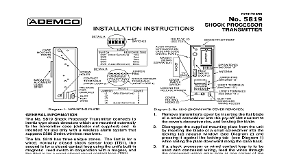
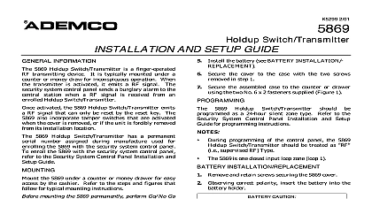
INSTALLATION INSTRUCTIONS use with QED control panels ONLY INFORMATION 5819WHS 5819BRS Shock Processor Transmitters a built in shock sensor and are intended for use with a wireless alarm system that supports Ademco 5800 Series wireless receivers built in shock sensor is used to detect forcible attack the surface to which it is mounted It is designed to window and door surroundings The sensor is normally closed but under shock conditions open circuit momentarily 5819 supports three unique zones known as loops 1 built in shock sensor loop factory wired to normally closed 2 built in magnetic reed switch in conjunction a magnet normally closed 3 externally wired closed circuit contact loop to TB2 U L installations a contact may not be more than 3 from the transmitter 5819 also has a built in cover tamper switch which when the cover is removed and sends a check to the control of Shock Protection area of coverage is 10 12 feet 5 6 foot radius can vary depending on the type of window or other surface to which the unit is mounted 4 98 PROCESSOR description that follows assumes that the unit will be as shown in the diagram with the magnet if located to the left of the unit The unit can be in any direction as long as the relationship of the to the magnet is maintained In addition the arrow on the built in shock sensor must face UP when unit is mounted change the shock sensor orientation gently push the away from its mounting hole until it can rotate Twist the sensor until the arrow is pointing UP when detector is in the desired mounting position then push the sensor until it is fully seated in its mounting mounting the transmitter permanently conduct Go tests see QED control instructions to verify signal strength and reorient or relocate the if necessary Remove transmitter cover by inserting the flat blade a small screwdriver into the pry off slot nearest to the decorative ribs and twisting the blade using a wired contact loop cut the thin breakout provided at the lower edge in the case wall to wire entry Mount the case back to a solid surface using the two provided in the unit holes in Diagram 1 using the unit reed switch mount a 5899 Magnet separately adjacent to the alignment marks the case see Diagram 1 using an external contact remove the battery if and connect a normally closed contact to If the contact loops are not used make no across the terminals 2 TEXT PRY OFF POINT MAGNET MARKS CASE 2 3 TERMINALS Detail 2 FOR ENTRY SWITCHES Detail PINS Detail 1 TERMINALS shock sensor Detail SENSOR Detail A 1 TIME Most Sensitive Least Sensitive 20ms B 2 Most Sensitive Least Sensitive LOOP 3 J4 J3 J2 J1 SENSOR LOOP 1 C arrow on sensor must UP when unit mounted INSTALLATION REPLACEMENT Remove the transmitter cover as described in Step 1 Observe correct polarity and insert the battery into the battery holder see Diagram Replace the cover engage the hooks along one and snap shut not bend the antenna Replace with 3V Lithium battery only CR123A Duracell DL123A Sanyo Varta CR123A or ADEMCO 466 CAUTION Risk of fire explosion and burns not recharge disassemble heat above 212 cid 176 F 100 cid 176 C incinerate Dispose of used batteries promptly Keep from children DIMENSIONS H x 1.5 W x 1 D RESPONSE TIME and SENSITIVITY Set response time using the DIP switches use the tip a pen pencil SW1 sets a response time of 1ms SW5 sets a response time of 20ms For a time of 0.5ms set all DIP switches to OFF Table 1 Set the pulse count jumper see Table 2 The pulse is reset 3 seconds after the first pulse detected is an LED on the PCB which flashes rapidly on Make the device highly sensitive for the of enrolling the shock sensor loop TB1 into system turn SW 1 on and put jumper on J1 After device has been enrolled adjust settings as in steps 1 and 2 above THE TRANSMITTER SERIAL NUMBER 5819 Shock Processor has a unique factory set number assigned during manufacture that must be by the QED control before usage in the system addition each zone loop of the transmitter must also programmed at the control panel during installation programming note the following The battery must be installed before enrolling Assign each loop to an individual zone number and Input Type 3 Supervised RF 1 built in shock sensor 2 built in magnetic reed switch 3 externally wired closed circuit contact To fault the loops when prompted 1 Flip the unit upside down then right side up activate the sensor 2 Bring the magnet close to the reed switch pull the magnet away to open and the reed 3 Open and close the contact according to its keypad will beep to confirm reception of each Test the unit after enrolling into the system using QED control test procedure THE INSTALLER maintenance and inspection at least annually by the installer and frequent testing the user are vital to continuous satisfactory operation of any alarm system The should assume the responsibility of developing and offering a regular program to the user as well as acquainting the user with the proper and limitations of the alarm system and its component parts Recommendations be included for a specific program of frequent testing at least weekly to insure the operation at all times TO THE FOR THE QED WITH WHICH THIS DEVICE IS USED FOR WARRANTY AND FOR DETAILS REGARDING THE LIMITATIONS OF THE ENTIRE SYSTEM D IVISION OF PIT T W AY C OR POR AT ION Ei l een W ay Sy os s et N ew Yor k 11791 opy r i ght 1997 Pi ttw ay C or por ati on 4 98