Ademco - 5850 Wireless Glass Break Detector

File Preview
Click below to download for free
Click below to download for free
File Data
| Name | ademco-5850-wireless-glass-break-detector-7653081294.pdf |
|---|---|
| Type | |
| Size | 1017.91 KB |
| Downloads |
Text Preview
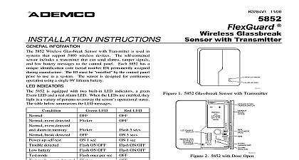
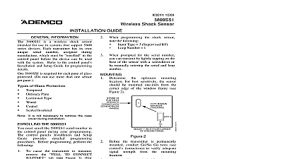
Several of you have written us to ask that we reconsider this decision We have Tech Man Subscriber apologizes for any misunderstanding that has arisen due to our recent to have our technical information removed from the Tech Man web site You appreciate that one of our key concerns is to provide installing security dealers with and accurate information on our products and we were concerned about the data to the Tech Man web site For obvious reasons we also do not wish unauthorized to have access to information on installing and configuring ADEMCO These concerns were what prompted us to ask Tech Man to stop posting installation instructions and user manuals will not require Tech Man to remove the ADEMCO data ADEMCO however is responsible for the operation and maintenance of this site thus we cannot guarantee timeliness or accuracy of the information posted on the Tech Man web site data about our products You may request a PIN number for access to the Technical Support web site and FAXBACK system you need assistance on troubleshooting or if you have other technical questions our products not addressed in the information posted at our web site please contact Technical Support at 800 645 7492 ADEMCO web site is located at www ademco com and contains accurate you for understanding Lustig 4 97 Break INSTRUCTIONS INFORMATION 5850 Glass Break Detector Transmitter is intended for use in systems which support 5800 wireless devices The detector includes a transmitter which can send alarms tamper and low battery messages to the panel Each 5850 has a unique identification code serial number ID permanently assigned during manu The ID must be learned by the control prior to usage in the system The detector is designed for operation using a single 9V lithium type battery Technology 5850 is a dual technology device that acoustically senses both sound and shock waves associated with glass The detector features separate microphones for sound audio and shock referred to as flex The audio detects the high frequency of breaking glass The flex microphone detects ultra low frequencies generated by a blow to a glass window Since both forms of energy must occur at the same time for a valid condition to be initiated by the device the likelihood of false alarm indications is kept to a minimum Indicators built in LED indicators permit local adjustment and monitoring when enabled via the orange LED ENABLE switch This switch is accessible when the cover door is open When a shock is detected the yellow FLEX lights When the sound of breaking glass is detected the green AUDIO LED lights When both shock and are detected the red ALARM LED lights LEDs normally light momentarily Memory 5850 also features an alarm LED latch switch which causes the LEDs to remain latched when activated This is during testing and in multiple detector installations where identifying units that caused an alarm could be difficult enable alarm memory Remove the cover assembly see step 3 of the Mounting section Move the alarm LED switch to the ON position Replace the cover assembly of Glass Protection Tempered Glass Laminated Type Glass Ordinary Plate Glass Wired Plate Glass 5850 is not recommended for protection of areas of less than 10 7 8 x 10 7 8 PROCEDURE to the specific sections for details on each of the following steps Install the battery See Installing the Battery section Adjust the detector sensitivity See Adjusting Sensitivity section Learn the detector serial number using the control panels programming procedure See Learning the ID section Mount the detector See Mounting section Test the detector See Testing Alarm Operation section THE INSTALLER maintenance and inspection at least annually by the installer and frequent testing by the user are vital to continuous operation of any alarm system installer should assume the responsibility of developing and offering a regular maintenance program to the user as well as the user with the proper operation and limitations of the alarm system and its component parts Recommendations be included for a specific program of frequent testing at least weekly to ensure the system proper operation at all times THE BATTERY Notes Use only UltraLife model U9VL J 9 volt lithium battery Observe polarity When replacing the battery wait at least 30 seconds after removing the old battery before If a low battery message is displayed at the keypad and you suspect that the battery is not truly low remove battery wait at least 30 seconds then reinstall the battery and re test the transmitter the new one Open the detector cover door Check battery polarity orientation before installing the battery into the battery holder with terminals the ledge with embossed polarity markings Press the back end of the battery down until it is securely in the holder Close the cover door Wait at least 30 seconds to allow the detector to warm then test the unit to ensure proper operation remove the battery pry up the back end of the battery a screwdriver or similar tool until it can easily be SENSITIVITY With the detector in the approximate mounting location open the cover door opening and closing the door can cause the to alarm An alarm can also occur if the LED switch is moved too forcefully Slide the LED ENABLE switch in the direction of the arrow an orange tab will protrude from the Using a screwdriver adjust the sensitivity control fully maximum sensitivity Turn on all heating air conditioning systems and other in the detector vicinity the yellow FLEX LED for about one minute POLARITY SWITCH LED SWITCH ENABLE this screw remove cover Random LED flashing indicates the detector is sensitive to the subsonic sounds of operating equipment Slowly the sensitivity control counter clockwise until the point at which the flashing stops After adjustment close the cover door THE TRANSMITTER ID 5850 serial number must be learned by the control before usage in the system The control unit installation provide detailed programming procedures for learning transmitter serial numbers Before do the following Install the battery if not already installed Observe polarity Remove the cover assembly see step 3 of Mounting section When programming this transmitter note the following Type 3 Supervised RF Loop Number 1 fault the detector when prompted momentarily press the test switch located on the exposed transmitter PC The keypad will beep to confirm the signal Wait 3 6 seconds before pressing the second time Test the detector after learning into the system Refer to the Testing Alarm Operation section 2 Determine the optimum mounting location noting the following Mount on the ceiling or on a wall at least 7 feet from the floor Mount such that the detector has a direct unobstructed line of to the protected glass Mount no more than 25 feet from the farthest protected glass Make sure there are no intervening partitions curtains etc that block the transfer of shock or sound waves If window dressing is present it will absorb sound energy breaking glass In such cases the detector should be between the protected glass and the window dressing Avoid locating the detector near sources of ambient vibration or such as air conditioners fans blowers air ducts or Avoid locations where furniture can be moved so that it blocks detector line of sight to the glass Mounted ceiling Mounted on wall top view Avoid locations where a door can be open or closed such that it blocks the detector line of sight to the glass Avoid locations near doors or windows that ma