Ademco - 645 Fire Mini Modularm System

File Preview
Click below to download for free
Click below to download for free
File Data
| Name | ademco-645-fire-mini-modularm-system-6571293840.pdf |
|---|---|
| Type | |
| Size | 1.32 MB |
| Downloads |
Text Preview
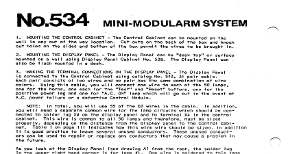
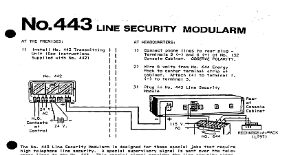
No 645 wsmv MINI MODULARM THE CONTROL CABINET ControICab inet be mounted bottom wall box permit an out of wires way THE DISPLAY PANEL No 640 Di sp I ay Pane I ca n be Display been prewired Display of Ademco mounted surface U L a wall Must be run 3 4 No 643 Junction Must not exceed Display Junction Display mounted No 539 Cabinet all THE JUNCTION BOX Display be concealed must be connected recessing wall wall by an adjacent Display Junction on Page 3 TEMINAL CONNECTIONS BETWEEN THE DISPLAY PANEL AND THE JUNCTION BOX Wiring so on with connected orange one section Wiring green each pair white another arranged color pair connected numbered Display normal has upper common screw all Wire Key shows THE TERMINAL CONNECTIONS FROM THE JUNCTION BOX TO THE CONTROL CABINET Junction connected any one conductor duplicate She Underwriters Control conduit be placed not have un it put break of service 31 No 543 cables match Control of of wires Control Display Bring Junction 1 BBOULD BE THE dual upper Control common each of There connect use FFre Control Control one exception colored must be sized circuits Control Junction Wiring shown Color Coding distance you know d istance complete separate wiring X4 manner as and 4 as a guide other Con matching Wiring proper Control X4 a common wire and Control 2 I NG THE POWER SUPPLY No 664 Power Supply ead vo I ts 4 amps the white black an Energy Pack and 96 M Rechargeable Control energy connects ot and 2 and 3 of 96 M Rechargeable energy I d be connected I 2 and 3 on bottom connected POLARITY na I 5 of i ne I To conform AH should NFPA 72C 60 hours standby are added within hours 96 M No 493 Rechargeable described Figure a standby THE TELEPHONE LINES 2 and so on Telephone of I must observe positive second upper negative HORNS REMOTE TEST SWITCH REMOTE RESPONSE SWITCH may be placed No 518 wire normally momentary momentary to X5 X3 normally any be placed 80641 Display 6 volt be placed any 8064 375 any to X4 I NG cold water attached provided as subscribers added must be made when equipment may be added as needed at a time No 536 Control must be used with cabinet F icjure No 537 Subscriber must be used Mini Modularm No 641 Fire Modules may be module needed pro When wiring complete a permanent Wiring Control power Catalog amp s o blo protects as 28 volts output ma