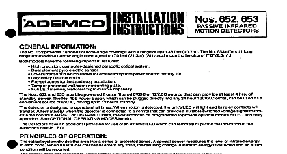
Ademco - 652-12-653-12 Passive Infrared Motion Detectors Installation Instructions

File Preview
Click below to download for free
Click below to download for free
File Data
| Name | ademco-652-12-653-12-passive-infrared-motion-detectors-installation-instructions-8401752639.pdf |
|---|---|
| Type | |
| Size | 1.65 MB |
| Downloads |
Text Preview
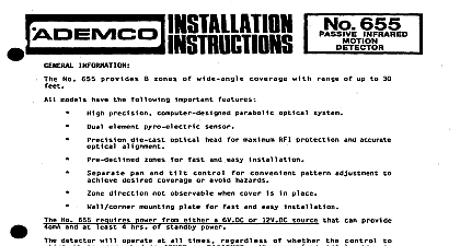
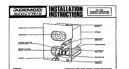
GENERAL INFORMATION No 652 12 provides 18 zones of wide angle coverage with a range of up to 35 feet 10.7m The No 853 12 offers 11 long zOnes with a narrow angle coverage of up to 70 feet 21.3m At typical mounting heights of 7 2.3m models have the following important features High precision computer designed parabolic optical system Dual element pyre electric sensor Low current drain which allows for extended system power source battery life Quiet relay operation Preset zones for fast and easy installation Tamper protected wall comer mounting plate Full LED memory walk testinightdisable Nos 652 12 and 653 12 must be powered from a filtered 12V DC source that can provide at least 4 hrs of power detector is designed to operate at all times When motion is detected the units LED will light and its relay contacts will Alternatively when the detector is connected to a control that can provide a suitable switched voltage signal to the control ARMED or DISARMED state the detector can be programmed to provide optional modes of LED and operation See OPTIONAL OPERATING MODES herein Detectors have an additional provision for use of an external LED which can remotely duplicate the indication of the built in LED OF OPERATION optical system divides the area into a series of protected zones A special sensor measures the level of infrared energy each zone When an intruder crosses or enters any zone the resulting change in infrared energy is detected and an alarm will be reported sensor does not respond to visible light or changes in the background temperature of the room a passive infrared device employs no transmission of any kind any number of units may be used in the same area infrared energy does not penetrate most building materials even window glass so the unit reponds primarily to human inside the room CONSIDERATIONS AND TYPICAL LAYOUTS 652 12 The pattern of protection provided by the 852 12 includes nine main zones which span an angle of approxi 90 and nine downward zones aligned in the same direction horizontally as the main zones See Diagrams 1 and 2 optical system has been designed to give a coverage range of 35 10.7m based upon a typical mounting height of 7 However the unit may be mounted at any height between 6 1.8m and 9 2.7m with modified range coverage as in Diagram 2 653 12 The pattern of protection provided by the 653 12 includes eleven zones positioned in a pattern which is ideal for protection of hallways corridors aisles or narrow rooms pattern consists of 3 main zones three intermediate zones angled slightly below the main zones and five downward See Diagrams 3 and 4 optical system has been designed to give a coverage range of 70 21.3m based upon a typical mounting height of 7 However the unit may be mounted at any height between 6 1.8m ind 8 2.4m to achieve other patterns of cover as shown in Diagram 4 Zone Caution Note in Diagrams 2 and 4 that for certain mounting heights there are indicated zones within a person could be moving and not be detected by any of the unit coverage zones In general these dead zones are to be present between the intermediate and main zones or between the detector and the downward zones as the unit height is increased 5 indicates protection ranges for the 652 12 and 653 12 at detector mounting heights of 6 1.8m to 9 2.7m a Mounting Location the Nos 652 12 and 653 12 Passive Infrared Detectors respond to changes in energy which occur when an moves into or out of a zone best coverage will be obtained if the mounting site is selected such that the likely direc of intruder motion is ACROSS the pattern See Diagrams 8a b and c a hallway aisle or narrow room a No 658 l 2 unit should be aimed directly down the center of the area the intermediate will prevent an intruder from avoiding detection by following the wall See Diagram 7a alternative approach is to angle the m n zones from See Diagram 7b direct viewing by the unit of heat sources such as radiators heating ducts direct sunlight etc AND WIRING I R units are remarkably resistant to false alarm hazards but the following recommendations should be observed locating unit where central heating radiators live fires or heating outlet ducts could be within the protective zones locating the unit in direct sunlight or directly above strong sources of heat locating unit on unstable surfaces running alarm wiring close to heavy duty electrical cables Be careful during installation or adjustment NOT TO TOUCH THE REFLECTOR OR SENSOR SURFACES Mount the wall plate to a firm and vertical surface flat on wall or in comer as shown in Diagram 8 at the recom height see previous section Orfent the plate so that the rectangular cutout in the plate is at the bottom If is provided from a hole in the mounting surface locate the mounting plate so that the wiring hole is centered within the rectangular cutout in the plate and the bottom edge of the plate is positioned in line with the cen of the wiring hole See Diagram 8 Detail A This will align the wiring hole with the wiring entry in the case when the is secured holes should be no larger than 6 in diameter Remove the front cover from the detector by loosening the retaining screw Attach the unit to the wall plate as follows Engage all four hooks on the wall plate into the slots on the rear of the See Diagram 8 and secure the unit to the wall plate by pressing downward After wiring replace front cover and secure retaining screw With front wver secured in place unit is locked to wall mounting plate To detach unit from wall plate front wver be removed first Connections the wire entry plug and the wiring entry access at the lower rear of the case carefully feed the wires through the entry along the underside of the terminal block Avoid contact between bare conductors and the circuitry located on the rear of the vertically mounted printed circuit board unnecessary splices and loops within the unit Check all connections carefully Diagram 9 for connections which should be made in this order Alarm Relay and Tamper Terminals To connect a closed circuit protective loop see diagram Connect tamper circuitry as desired Control Signal Terminal and Options See OPTIONAL OPERATING MODES If one of the options is to be run the necessary control lead s between the detector and the main control and cut the required jumpers Optional Remote LED Post Connect as shown in diagram Also cut the YELLOW jumper on the circuit board Note side of the LED that is not connected to the remote LED post may be connected directly to the DC source ground the wire length is shorter OBSERVE POLARITY Input 12V DC and Terminals Connect these terminals to a 12V DC source that can provide 17mA wntinu Observe polarity Continuous auxiliary capacity of applicable 12V Ademw controls is as follows 4CtOmA 3OOmA 550mA 220mA 500mA 500mA LED will light and the relay contacts OPERATING MODES shipped from Ademw each detector LED and relay will function together at all times regardless of whether the main system control is ARMED or DISARMED While motion is d e d transfer used with a control that can provide a suitable switched voltage to the detector control signal terminal to signal the control is ARMED or DISARMED the detector can be programmed by cutting various combinations of jumpers the unit circuit board to provide optional modes of operation as described in this section voltage for CONTROL SIGNAL Terminal Before cutting jumpers make sure that the control can provide the proper switched voltage signal to the SIGNA