Ademco - 655 Passive Infrared Motion Detector Installation Instructions

File Preview
Click below to download for free
Click below to download for free
File Data
| Name | ademco-655-passive-infrared-motion-detector-installation-instructions-4813960572.pdf |
|---|---|
| Type | |
| Size | 1.44 MB |
| Downloads |
Text Preview
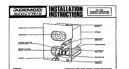
GENERAL INFORMATION No 655 provides models have the zones of wide angle with of up to 30 precision element pyro electric for maximum RF1 protection accurate and easy desired and or avoid hazards direction observable when cover place plate and easy No 655 requires and at 4 hrs of standby power from either 6V DC or 12V DC source provide detector will connected unit at all whether control ARMED or DISARMED Whenever while motion will its will OF OPERATION optical measures an alarm condition divides zone the enters area a series protective special each zone When an intruder detected sensor not visible changes background a passive of units may be used in same area any kind not penetrate the unit only motion building window CONSIDERATIONS AND TYPICAL IAYDDTS pattern an angle of 75 and three downward zones as shown in Diagrams 1 and 3 main zones which protection 655 entire may be right to 20 optical height of 7 and 9 has been designed achieve a proper 30 pattern give proper coverage may be mounted at any height a typical be mounted obtain range of 9 high as 12 30 a particular unit desired optical the bracket sensor surfaces be used optical may be tilted obtain both release set Combinations metal a ridge shown in Diagram 3 mounting adjust and Do not touch the reflector desired provided on the casting Diagram 2 Caution moving and not be detected Diagram 3 that several zones within any of unit dead zones are apt its pattern be present unit a person zones A MOUNTIN LOCATION No 655 Passive occur when an intruder moves into or out of a zone obtained ACROSS the pattern Detector motion mounting selected Diagram 4a b and c energy changes will AND YIRIWG be observed but could be within where central protective outlet heat unit direct directly strong on unstable alarm wiring heavy duty electrical wiring prevent complete of air movement and drafts wire entry opening case should PIR unit sealed Be careful SENSOR SURFACES WHEN POSITIONING THE HEAD ASSEMBLY GRIP THE DIE CAST ONLY AS SHOWN IN DIAGRAM 2 adjustment NOT TO TOUCH THE REFLECTOR with 5 wall that mounting a firm vertical previous are at bottom wall or wiring bottom a hole wiring pl ate mounting case when hole unit mounting will secured front by loosening the special mounting holes at done head screws of the retainer not already wall bottom hex gain access mirror may result screws Diagram 5 and secure not detector lower hooks on wall plate with detector left wall from unit damage only wires along wiring underside conductors of case and carefully printed metal parts contact printed within unit all Diagram 6 Connections be made in Terminals provide 6 shows how to connect a closed circuit a 6V DC or 12V DC source continuously typical polarity controls 1022 1023 1024 1025 JnA InA mA InA 330R 25 34OR 25 332R 50 342Rk50 4080 mA mA InA 12V DC operation necessary cut BLUE jumper provided some typical controls 1022 12 1023 12 1025 12 4080 12 mA mA mA mA at walk test minutes dfter before attemptinq and gmnent adjustment cleared OFF during testing all people do this procedure detector some business be conducted with will protective prevent unwanted alarms being sounded protected more a DC Voltmeter positive of printed extreme Multimeter Ohms per Test Point meter should be connected on the connector meter should be set 2.5V DC the detector DC level