Ademco - 674 Select-A-Line

File Preview
Click below to download for free
Click below to download for free
File Data
| Name | ademco-674-select-a-line-5109236874.pdf |
|---|---|
| Type | |
| Size | 1.08 MB |
| Downloads |
Text Preview
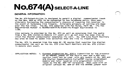
No 674 SELECT A LiNE No 674 Select A Line 669 or 670 communicator be connected designed permit lephone ca I 1 i ng are made over digital i rs as event ines one provided No 674 as well assurance will out over same which audio digital 659 Line Fault Monitors also be used speed a No 676 No 674 well powered No 659 Line Fault Mon tors same 6 V DC source No 676 Listen In digital when used The No 674 cannot Nos 679 669 No 669A and 670A 669 and 670 Digital used with NOS 612 or 662 Dialers version compatible can new No 674A will be used screw programmed 670 version No 674A W ill page 180 No 674A the digital 674 alternately not one communicator activated not second attempt I I be made on second attempt nes The first ne number i ve next attempt made via I I be made on ss of made on etc 674 provided both well and phone i nes provided used with No 659 Line Fault Monitors dial without i ne has been detected out of service No 674 automatically digital will attempt dial an out a No 676 Listen In sends No 674 audio i nes used with No 676 out which digital i ne a ca I I was camp leted communicator not alternate ease of provided digital 674 Select A Line be slipped cabinet ability a housing which other upper edge of No 674 cabinet be close Diagram Diagram of No 674 come already Other unit Wire Splices packaged with NO 674 be extended No 301 solder provided 1ocal handse t with wiring Connect and extend i ck d i sconnect a cold water digital lephone i ne barrier handset made 659 Line Fault Monitors Diagram 659 and extend i ne posts No 674 as Signal to No 674 YELLOW and GREEN leads No 659 shown on Dia and YELLOW selected respectively dTgital and WHITE digital Connect post ve power V DC power Connect negative post switched Connect digital 676 Listen In No 676 Listen In quick post Diagram and extend No 676 Power and Switched Power Posts posts provided making other modules needed 6.4 3.8 cm grams 2 oz V DC Switched 676 Listen In ma Communica tor ng Current LI DETAIL RIGHT MOUNTING DETAIL 674 1 j 5 TELEPHONE TO COMMUNICATOR I 18 I I I g II T I HANDSETS No 2 HANDSETS No 2 1 FAULT SIGNAL 2 FAULT SIGNAL LOGIC LEVEL SIGNAL POST No 659 FDR LINE No 1 IF USED LEVEL SIGNAL POST No 659 FOR LINE No 2 IF USED TO COLD WATER PIPE GROUND POWER NEGATIVE BLACK SELECTION CONTROLIWHITE 4 TO POST TO POST DIGITAL No 669,670 SWITCHED POWER GRAY LEAD WITH QUICK DlSCONNECT FURNISHED REQUIRED POWER No 676 IF USED 1 lnstal lation and Wiring