Ademco - 685 Telephone Line Noise Filter Installation Instructions Supplement
File Preview
Click below to download for free
Click below to download for free
File Data
| Name | ademco-685-telephone-line-noise-filter-installation-instructions-supplement-7642031895.pdf |
|---|---|
| Type | |
| Size | 1015.70 KB |
| Downloads |
Text Preview
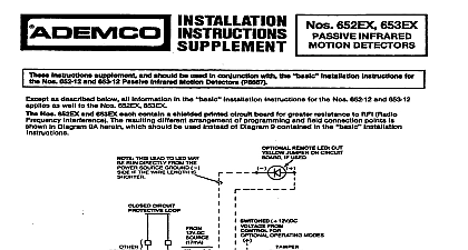
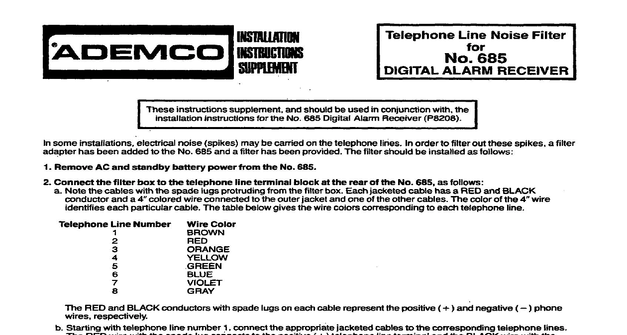
Telephone Line Noise Filter 685 ALARM RECEIVER instructions supplement and should be used in conjunction with the instructions for the No 665 Digital Alarm Receiver P6206 some installations electrical noise spikes may be carried on the telephone lines In order to filter out these spikes a filter has been added to the No 685 and a filter has been provided The filter should be installed as follows Remove AC and standby battery power from the No 686 Connect the filter box to the telephone line terminal block at the rear of the No 685 as follows Note the cables with the spade lugs protruding from the filter box Each jacketed cable has a RED and BLACK and a 4 colored wire connected to the outer jacket and one of the other cables The color of the 4 wire each particular cable The table below gives the wire colors corresponding to each telephone line Line Number Color RED and BLACK conductors with spade lugs on each cable represent the positive and negative phone respectively Starting with telephone line number connect the appropriate jacketed cables to the corresponding telephone lines RED wire with the spade lug connects to the positive telephone line terminal and the BLACK wire with the lug connects to the negative telephone line terminal The spade lugs connected to the 4 colored wires must be connected to the housing of the No 685 Position the spade of both the BROWN RED pair and the ORANGE YELLOW pair under the head of the screw located at the left end the telephone line terminal block In the same manner secure the spade lugs of the GREEN BLUE and VIOLET wire pairs under the head of the screw located at the right end of the terminal blodc Connect the housing of the No 685 io a gqod cold water pipe ground Connect the telephone lines to the terminal strip on the filter box 8s follows 1 Ring 2 Ring Ring GROUND GROUND Ring SubatMe new pair of standby battery cables with RED and BLACK wires that accompany the filter box for those provided with the No 685 These cables incorporate capacitors to filter out voltage spikes arriving via the battery cables smaller black wires with the spade lug should be secured under the head of one of the screws on the side of the 685 Also change the Remote Alert cable WHITE and BLACK wires if used new cable provided incorporates capacitors to filter voltage spikes When this cable is used only voltages of 12 volts DC or less may be used to power the remote sounder single spade lug attached to the two BLACK wires should be secured under the head of one of the screws that secure back of the No 665 power to the No 685 Press the SYSTEM TEST button to initiate a test of the telephone lines If a telephone line shows up check the polarity and or voltage of the corresponding telephone line at the rear of the No 685 DEVICE MANUFACTURING DIVISION OF PImAY Eileen Way Syosset Neti York 11791 1982 PllTWAY