Ademco - 686 Parallel Mode Conversion of No 686 Printer Used with No 685 Digital Alarm Receiver Installation Instructions Supplement

File Preview
Click below to download for free
Click below to download for free
File Data
| Name | ademco-686-parallel-mode-conversion-of-no-686-printer-used-with-no-685-digital-alarm-receiver-installation-instructions-supplement-2768340591.pdf |
|---|---|
| Type | |
| Size | 975.09 KB |
| Downloads |
Text Preview
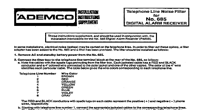
No 685 ALARM RECEIVER These instructions supplement and should be used in conjunction with the instructions for the No 685 Digital Alarm Receiver P8208 reduce the possibility of noise interference cable is recommended the No 685 Receiver and No 686 Printer use of the accompanying parallel of No 686 Printer OKIDATA MODEL 82 to Parallel Mode Disconnect power from the printer Remove the upper cover of the printer Refer to OKIDATA Operator Manual Fig 3 3 on page 8 Remove the access cover Remove the platen knob by pulling it to the right Remove the two screws securing the upper cover These are located in recessed wells at the front corners of the printer Remove the upper cover by lifting it at the front Set the dipswitches located next to the LINE FEED pushbuttons to the following positions l 4 OFF 5 6 8 OFF Replace the upper cover Connect the accompanying parallel printer cable to the printer parallel interface connector Disconnect all power from the No 685 AC and standby battery Configure the No 686 to operate with a parallel printer reter to the No 685 Memory Card Set Up procedure in the 665 installation instructions Move the jumper plug to jumper pins 1 2 of P7 lf the use of the serial printer part is being discontinued move the jumper plug on P9 to connect pins 4 5 Connect the remaining end of the accompanying cable to the 5105 PARALLEL PRINTER connector on No 685 The cable has a lugged wire extending at each end If the wires are not already tied to metal connector shells the free wire at the No 665 end to the chassis of the No 685 use the screw located below the J105 PRINTER connector The free wire at the printer end will not require any connection MANUFACTURING OIVISION OF PVITWAY CORPORAllOW Eileen Way Syosset York 11791 198 2 PIllWAY