Ademco - 688-12 Opening-Closing Switching Module Installation Instructions

File Preview
Click below to download for free
Click below to download for free
File Data
| Name | ademco-688-12-opening-closing-switching-module-installation-instructions-3128796450.pdf |
|---|---|
| Type | |
| Size | 1.06 MB |
| Downloads |
Text Preview
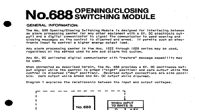
No 688 l 2 MODULE INFORMATION No 666 12 Opening Closing Switching Module is designed for interfacing between an alarm processing center any other equipment with a 12V DC electronic output and a digital communicator to signal the communicator opening and closing messages as the control is disarmed and armed It permits such an electronic input to a higher energy output load alarm processing centers such as the 1022 l 2 and 102512 may be used regardless of the method used to and disam 6V to 12V DC activated digital communicator with or message capability may be used No 669 or 676 connected as described herein the No 666 12 provides a 12V DC continuous output signal while the control armed position and zero output while the control is disarmed position Reversed output wnnec are also possible zero output while armed and l2V DC output while disarmed 1 explains the relationship between the input and output voltages system 688 12 SIGNAL DC POWER Is 12v 1 INPUT OUTPUT RELATIONSHIPS No 666 12 can also be used to energize a relay to turn lights on at entry time for instance OTHER APPLICATIONS herein and Diagram 3 AND WIRING Disconnect the control panel battery and AC power Install the No 688 12 In the control panel cabinet A mounting lip is provided on the No 666 12 which can be over the cabinet edge without interfering with the closing of the cabinet cover Run wiring and make connections to the particular control and communicator to be used as indicated in Dia 2 Reconnect the power sources disconnected in Step 1 and check the operation of the dig l communicator the central monitoring station when the system is armed and disarmed TO PROCESSING CENTERS1 14 V IF E CONNECTIONS TC COMMUNICATORS 670 669 6 2 TYPICAL FOR OPENING CLOSING SIGNALS FROM APC the control panel is ARMED the communicator will send its programmed message as the signal the No 669 its Channel B PROGRAMMED CODE will be sent With the No 678 the OPEN CLOSE or channel will be sent as selected the control panel is DISARMED the communicator will send its RESTORE or OPENING message as the signal For the No 669 a or as chosen will be sent For the No 676 a will be sent for an channel The channel and then a will be sent for a RESTORE channel If the No 686 12 ORANGE lead is connected to the communicator in lieu of the VIOLET lead operation will reversed For a No 669 communicator for example ARMING CLOSING will send the RESTORE and DISARMING OPENING will send the PROGRAMMED Channel B CODE should be noted that a No 1022 l 2 Alarm Processing Center can provide such operation without use of No 688 12 The No 1022 l 2 installation instructions describe how to connect the APC ORANGE to a No 669 digital communicator opening Programmed Code and closing Restore Code signals APPLICATIONS No 668 l 2 can also be used to control a load minimum resistance 500 ohms such as a relay The load may connected between the ORANGE or VIOLET lead and the negative side of the power supply Both leads may connected to a load one will be ON while the other is OFF For example Diagram 3 shows how an alarm center such as the No 1025 l 2 can be used to turn on lighting during the entry delay period SUITABLE RELAY AND ENCLOSURE COIL RESISTANCE 56d OHMS REGUIRED BY 2 TERMINAL AS LEAD OF No 666 12 14 d 20 LEAD ON TERMINALS IF AVAILABLE REMOVE CON AND STRIP ENDOF 3 TO TURN LIGHTS ON DURING ENTRY DELAY PERIOD 3 1 4.4 cm cm from control 12V DC WHlTE lead 336K ohms ArmefY Level Zero less than 0.4V Level 12V greater than 5V VIOLET lead Inverting f 12V when input is Zero lead Non inverting Zero when input is Zero should be connected to VIOLET and or ORANGE lead and negative of supply Minimum resistance of load 566 ohms