Ademco - 758 Keypad Programmable Tape Dialer

File Preview
Click below to download for free
Click below to download for free
File Data
| Name | ademco-758-keypad-programmable-tape-dialer-1098264375.pdf |
|---|---|
| Type | |
| Size | 1.62 MB |
| Downloads |
Text Preview
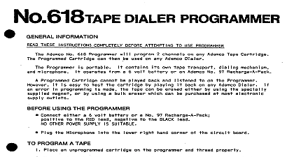
INSTAllATiON OIAUR 758 INPORMATION No 758 Keypad Programmable an alarm drive are event in dial up input priority is No 758 Dialer used communicate will be dialed unit to 4 telephone be programmed be easily user channel 14 digits integral user may also program well number of and 2 or all may be changed any an stored nonvolatile and unaffected may be cleared mode stored keypad nonvolatile Program mode may be reviewed dialer momentary aided a be audio message played dialer each channel an may originate normally open an AND WIRING outside ordered a special Carefully plastic extend cartridge deck below motor Rotate cartridge position deck Deck OF MOTOR LOCATING HOLE AND SCREW HOLE IN DECIC Move cartridge screw hole deck deck hole cartridge When deck place with hole 6 x been cartridge provided Guide shown Figure around posts magnetic Post TAPE AROUND POSTS AND MAGNETIC HEAD Gently should Figure shaft be place hold posts over against magnetic 3 TAPE AROUND CAPSTAN contact Figure made by oerforming away magnetic pressure pad gently PAD CONTACT WITH TAPE Connections auxiliary signal alarm any Figure DC power Alarm and 2 completely one another a voltage be used on either nonnally NORMALLY OPEN CONTACTS 10 CH l used CU 2 and 13 CH 2 I NORMALLY CLOSED CONTACTS l jumper Channel 2 2 2 and 13 CH 2 15 GND with 10 CH l 15 with jumper used Terminals Terminals Terminals A VOLTAGE TRIGGER IS USED VDC 10 V min have a common DC ground Vmax Terminal 1 V Trigger 2 V Trigger Terminal Terminal TEST mlel r LOCAL NO 675 GROUND START REQUIRED 5 CONNECTIONS AND SWITCH DESIGNATIONS Local Handsets built No 758 handset No 758 will central a call prevent Terminals and 5 to Cord which made via No RJ31X and 3 to Ademco No 620 Direct telephone an alternative 3 may be connected and 5 connected parallel flying and 3 and GREEN to Terminal connected flying provided should connected an earth DC Power Supply RUN position RED and BLACK 1 sure RUN PROG connect DC power sure observe apply power Program mode dialer supply must be nominally 15 VDC and desired 12 Charger VDC between supplying 0.6 A during m4 BP4 Battery 7 8 and 16 for No 675 Ground Start Module as POWER coupler VDC when Vcc dialer active 65 mA provides Terminal and GND Terminal Maximum 65 mA VDC is available CP POWER START Terminal mA at 4.6 volts activate used wait provides high guaranteed 1.5 mA at 2.5 volts No 675 Ground Start Module volts DESGRIPTION AND PROGRbHING apply switch power