Ademco - 764, 764-6, 764-12 Ultrasonic Motion Detectors
File Preview
Click below to download for free
Click below to download for free
File Data
| Name | ademco-764-764-6-764-12-ultrasonic-motion-detectors-9475302816.pdf |
|---|---|
| Type | |
| Size | 1.76 MB |
| Downloads |
Text Preview
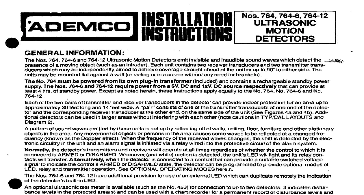
FADEMC I its own plug in and contains a rechargeable standby power INFORMATION Nos 764,764 6 and 764 12 Ultrasonic Motion Detectors emit invisible and inaudible sound waves which detect the g of a moving object such as an intruder Each unit contains two receiver transducers and two transmitter which may be independently aimed to achieve coverage straight ahead of the unit or up to 90 to either side The may be mounted flat against a wall or ceiling or in a comer without any need for brackets No 764 must be powered The Nos 764 6 and 764 12 require power from a 6V DC and 12V DC source respectively can provide at 4 hrs of standby power Except as noted herein these instructions apply equally to the No 764 No 764 6 and No the detector can provide indoor protection for an area up to of the two pairs of transmitter and receiver transducers 30 feet long and 14 feet wide A consists of one of the transmitter transducers at one end of the detec and the corresponding transducer at the other end on the same side of the unit See Figures 4a and 4b Addi detectors can be used in larger areas without interfering with each other note cautions in TYPICAL LAYOUTS and 2 pattern of sound waves emitted by these units is set up by reflecting off of walls ceiling floor furniture and other stationary in the area Any movement of objects or persons in the area causes some waves to be reflected at a changed fre known as the Doppler effect When the frequency of the received waves changes the shift is detected by the elec circuitry in the unit and an alarm signal is initiated via a relay wired into the protective circuit of the alarm system detector transmitters and receivers will operate at all times regardless of whether the control to which it is is ARMED or DISARMED Whenever and while motion is detected the unit LED will light and its relay con will transfer Atternatively when the detector is connected to a control that can provide a suitable switched voltage to indicate the control ARMED or DISARMED state the detector can be programmed relay and transmitter operation See OPTIONAL OPERATING MODES herein Nos 764 6 and 764 12 have additional provision for use of an external LED which can duplicate remotely the indication the detector built in LED optional ultrasonic test meter is available such as the No 453 for connection to up to two detectors levels in the protected area s and can be used with a chart recorder for a permanent record of disturbance conditions Complete instructions accompany the ultrasonic test meter Only late production versions of the No 453 two YELLOW ju mpers on their PC board are suitable for use with No 764 series detectors PRECAUTIONS the area to be protected carefully before installing any units Even though the detector contains circuitry to minimize effects there are conditions as described below which may appear as motion to the detector and result in unwanted When determining a location for the unit take care to avoid the following provide optional modes of indicates distur and CURRENTS such as created by space heaters air conditioning vents rising heat from radiators or baseboard heat and strong drafts such as those resulting from loose fitting doors and show windows or walls that shake when traffic passes the unit on a sturdy inside wall wherever possible SOUNDS from telephone bells or radiator valves located directly in the area to be protected OBJECTS such as house pets or other animals on the premises as well as hanging objects that tend to sway or doors that can be moved by air currents best location for the unit is 4 to 7 feet from the floor safely away from drafts CONSIDERATIONS pattern of ultrasonic waves set up by each pair of transducers in the detector is oblong and at maximum sensitivity has a range of up to 30 feet and a width of approximately 14 feet as shown in Diagram 1 a Actual coverage however is by these factors areas that have highly reflective surfaces coverage is greater because the surfaces are AND AIMING Each receiver can be aimed in the same direction as its paired transmitter or in a different Various coverage patterns can be obtained See Diagrams Wand Coverage up to 90 to either side may obtained REFLECTION and easily reflect ultrasonic waves Glass tile floors mirrors walls and most solid surface areas are considered surfaces containing soft sound absorbing material tend to reduce the range of the unit Examples of this kind of surface carpeted floors draperies heavy plush furniture etc AND TEMPERATURE Ultrasonic waves are affected by atmospheric humidity and temperature Between the and worst combinations of conditions range can change noticeably In general low humidity and high temperature the best longest range and high humidity and low temperature give the worst shortest range The actual range is a function of both these conditions PAIR PAIR TRANSDUCERS TYPICAL COVERAGE Transducer pair aimed straight ahead pair aimed to the side 1 b PATTERN VARIATIONS ONE TRANSDUCER PAIR and Receiver aimed in different relative to each other Aiming of unit other pair of transducers determine unit total coverage pattern LAYOUTS keeping in mind the aforementioned considerations and other factors mentioned below the installation may be laid out number of detectors may be placed in the same area without interfering with each other as long as the following basic rules are observed Do not direct units at each other unless the distance between them exceeds 69 feet Diagram 2a illustrates this Units may be placed on opposite walls or the same wall provided their centers are offset at least 15 feet from each if aimed straight ahead Diagram 2b illustrates this Ceiling mounting is useful in some applications See Diagram 2c Back to back installation may be considered See Diagram 2d Don place units too close together as some range shortening can occur Note minimum spacings indicated in Dia 2a and 2b Pattern direction and shape is determined by aiming of transducers necessarily by direction unit faces 2 LAYOUTS TO 60 a 4 AND WIRING detector is designed for mounting flat against the wall or in a comer Mounting brackets are not necessary Diagrams 4a 4b show the locations of the mounting holes unit should normally be mounted with its long dimension vertical to permit the transducer heads to be aimed to the side straight ahead as required If desired however almost any mounting position may be used including ceiling mounting Connections wiring well with break away walkforsurface wiring is provided adjacent to the unit terminals See Diagrams 3a 3b 4a 4b Connections should be made in this order Terminals NO C and NC To connect a closed circuit protective system use terminals NO and C Note A tamper may be installed in the unit by using a TP 6 Tamper Pack instructions accompany it Remote Terminals GND and SIGare provided for optional wnnection an ultrasonic test meter such as No 453 used see instructions with the meter The No 453 is powered be powered from the detector power source For the No 764 6 or No 764 12 the GND connection must be taken from the negative DC power input the AC line via its individual transformer and see Diagram 3b 764 6 or 764 12 Only External LED Connect as shown in Diagram 3b Also cut the YELLOW jumper on the board see Diagram 4b Note The LED positive lead may be run directly from the