Ademco - 800LR, 801LR Assist-Alerts

File Preview
Click below to download for free
Click below to download for free
File Data
| Name | ademco-800lr-801lr-assist-alerts-9125803674.pdf |
|---|---|
| Type | |
| Size | 1.22 MB |
| Downloads |
Text Preview
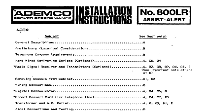
INDEX Section s A m Requirements Wired Activating D4 Transmitters C8 C9 D4 05 E at end D Chassis Cabinet Cl ta I Commun i cator Cord C4 C5 D C7 D3 A C Outlet A B C3 DI E Testing D 2 Unit 0 Standby A E GENERAL No 800LR and 80lLR Assist various covered a central request be automaticallv Assist 670 or 1690 A No 1320 Transformer optional No 80lLR digital Ademco No 1680 No 620 Direct Cord accompany unit No 800LR has 669 may be triggered Assist Emergency Switches used and 1692 which are wired open circuit with unit as Nos 269 and by radio as No 1690 Receiver a radio GREEN Indicator gggist is present out unit normally ON The POWER ON OFF switch OFF or AC is RED LED and a buzzer uhit a cal un t progress be pressed momentary abort at of GREEN Indicator unit on when TRANSMISSION switch been unit transmission has started OPERATION the unit PRELIMINARY CONSIDERATIONS a radio provide premises all telephone convenient NOT to be used Assist unit may be a Hr AC outlet should No RJ38X near not requested wire be used have larqe as unit any which a transmitter partially a radio metal premises completely more be used a final all premises signals ascertained addition WIRING See Diagram shipped Assist switches digital partially place screws chassis cabinet cabinet held place wiring barrier No 1320 Transformer shown diagram next not plug and 2 of digital Channel A B is GREEN jumper other not used not plug sure connect No 620 Direct as described be used be used and accompanying NON ABORT BLUE NON ABORT YELLOW jumper Post P3 Program addition channel No 620 Cord until other appropriate for Channel A WHITE communicator RED BLACK and YELLOW leads diagram communicator Cord Post PI Post P2 and NON or B eliminate next Channel connected on STORAGE open circuit of wired barrier be used in para le I 1 to shown diagram 620 Cord out wiring activating cable provided The diagram be secured digital a No screws another be used connect as bracke mounted used The No 1690 Receiver a rad i o transml positive power source voltage CH A or connection a receiver used B of communicator may be connected either no additional communicator appropriate cabi net unit a receiver net and out used wire routed high as possible FINAL CONNECTION AND TESTING advisable unwanted notify central accidently system sure I I be used unit


