Ademco - 970 Analyzers

File Preview
Click below to download for free
Click below to download for free
File Data
| Name | ademco-970-analyzers-2741569308.pdf |
|---|---|
| Type | |
| Size | 1.37 MB |
| Downloads |
Text Preview
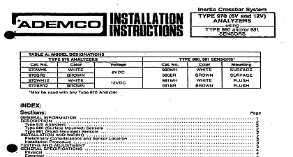
ADEMCOI Crossbar System TABLE A MODEL DESIGNATIONS 970 ANALYZERS No DC be used with any Type 970 or No 971 Analyzer No AND ADJUSTMENT and Diagrams A MODEL DESIGNATIONS B COVERAGE AND SENSITIVITY AUjusT ENTGijlijiilNES A 1 TYPE 970 ANALYZERS TIME PULSE INTEGRATOR SHOCK RESPONSES 6 2 TYPE 963 SENSOR INSTALLATION DETAILS 6 6 3 TYPE961 SENSOR INSTALLATION DETAILS 4 TYPICAL SENSOR LOCATIONS 6 5 FIELD CONNECTIONS WlTHOUT SEPARATE TAMPER LOOP 7 7 6 FIELD CONNECTIONS WITH SEPARATETAMPER LOOP INFORMATION Inertia Crossbar System Type 970 Analyzers accommodate any number of Type 961 and or 963 Sensors a maximum of 30 is recommended for ease of servicing The resultant forced entry shock detection can be used alone or can complement other forms of perimeter protection The system possesses the to detect attacks before an intruder gains entry to the premises analyzer will respond to blows applied to the surface s protected by the sensors A succession of small a smaller number of larger shocks a single attack or a fault in the sensor loop will trip the and place it in alarm System reset is accomplished by interrupting the analyzer power momentarily optional automatic reset has been selected during installation analyzer alarm contacts can be connected to any alarm panel with a closed circuit protective loop Type 970 Analyzers require 614V DC current 35 mA for their operation 970 Analyzers analyzer is furnished in a tampered housing containing an LED visible through the unit cover a sensitivity adjustment potentiometer and terminals for connection of a Two wire supervised sensor cir with end of line resistor b separate tamper loop if required c protective circuit the unit closed con open during alarm and d 8 14 V DC power Also provided is a jumper which can be cut to select optional reset analyzer contains a integrator processing circuit which has been designed for optimum to attempts at forced entry through most building materials See Diagram 1 The alarm trip level is after the sensing of a succession of light shocks e g gentle prying of a door or window or a smaller of heavier shocks e g hitting or pounding on the building structure A gross attack very large single or fault in the sensor loop will trip the system immediately The time pulse integrator circuit provides immunity to lower level occasional shocks such as may be caused by building expansion or contraction other transient occurrences the analyzer trip level is reached its alarm contacts will open and its LED will light The unit will re in alarm until reset by momentary interruption of power if optional automatic reset has been selected system will reset itself after about 5 seconds Type 983 sensor tampered housing contains a shock sensing module and terminals for connection of two wire end of line resistor supervised sensor loop and if required a separate tamper loop The housing the Type 983 is designed for surface mounting the 981 is flush mounted sensin su rf characteristics of the mounting surface and other field conditions See Diagrams 2 and 3 the heart of the sensing module is the inertia crossbar assembly A high inertia mass is mounted on a polished gold plated which straddles four other highly polished gold plated elements in such manner as to provide two parallel paths for the sensor circuit current with two sensing contact points in path Optimum long term stability and reliability are provided by this multiple path arrangement entry attempts typically produce vibrations which affect the contact points of the sensing module in crossbar assembly The resultant tiny and rapid variations in sensor circuit current are then processed by analyzer time pulse integrator If a series of shocks of sufficient intensity is sensed the trip level will be and the unit will go into alarm AND WIRING Considerations and Sensor Location the many types of building materials and construction methods used it is impossible to give sensor location information for any shock system Table B gives general guidelines for the diameter of DP that might be obtained under ideal conditions for each sensor when mounted on various number of sensors may be connected to a single analyzer but a maximum of 30 is recommended for better and ease of servicing The diameter of protection DP may be smaller where there are discontinulties in the mounting surface may be rotated up to 180 about its axis to facilitate mounting on a vertical horizontal or and to enable sensor operation in a NORMAL or DAMPED mode depending upon range as windows doors corners or joints between panels or cracks In these cases the sensors should be at 112 DP from the center of the gap See Diagram rl a b c d Where the opening exceeds the DP sensors around the edge as shown in Diagram 4 e Locate sensors at the most likely intrusion height relative to outside ground level Where the height of a wall l 112 DP use two rows staggered as shown in Diagram 4 f Sensors on surfaces BELOW outside ground level require half DP spacing Loose or rattling surfaces may give false shock signals In particular check windows for loose frames or Beams studs and electrical conduit increase shock transmission For example when protecting roof areas advantage of the shock transmitting properties of beams Sensors on window frames should be located 2 or less from glass Sensors on should be located at least 3 in from the frame See Installation Procedure Step 5b for in ormation Whenever possible divide the installation into separate zones using several analyzers This allows greater and aids in troubleshooting Where a wide variety of surfaces and materials must be protected that would make setting difficult con using Type 965 or 966 iatching Sensors in conjunction with a Type 972 Latching Monitor or Type 973 Latching Monitor The individual sensitivity of each sensor can then be adjusted for optimum Procedure the analyzer either near the main protective system control panel or within it double sided foam can be used wiring between the control panel analyzer and 88lected 88n8or locations as indicated in Diagram 5 or a separate tamper circu