Ademco - 973 Multizone Latching Monitors

File Preview
Click below to download for free
Click below to download for free
File Data
| Name | ademco-973-multizone-latching-monitors-2648750931.pdf |
|---|---|
| Type | |
| Size | 1.62 MB |
| Downloads |
Text Preview
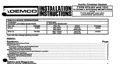
Inertia Crossbar System MONITORS 973 TENSORS AZ MODEL DESIGNATIONS number Latching Kits Sensor Type csn be ordered with white or brown housing The letters or follow the part numbers respec For example 985WH is a White Slimline Latching Sensor Latching Monitors Considerations and Sensor Location AND WIRING and Diagrams A MODEL DESlGNATlONS B COVERAGE AND SENSlTlVlTYADJUSTMENf LATCHING SENSORTlMElPULSE INTEGRATOR SHOCK RESPONSE LATCHING SENSORS INSTALLATION DETAILS SENSORS FOR USE WlTH TYPE 966 INSTALLATION DETAILS TYPICAL SENSOR LOCATIONS FIELDCONNECTIONS WITHOtJTSEPARATE TAMPER LOOP FIELD CONNECTIONS WITH SEPARATETAMPER LOOP 97315 INSTALLATION ll INFORMATION Inertia Crossbar System detects shocks generated by an intruder attempting to break through a protected Sensors installed at key locations process these impulses and transmit an alarm signal to the Type Latching Monitor in any combination For ease of servicing however a maximum of 30 sensors per 973 is recon If annunciation is required for more than 25 Latching Sensors some combination of 973 Kits is recom zone annunciation is provided by LEDs on ari AN5TM available in displays of 5,15 or 25 indicators The forced entry shock detection system can be used alone or can complement other forms of perimeter The system possesses the ability to detect attacks before an intruder gains entry to the premises Inertia Crossbar System Type 973 Latching Monitors can supervise and annunciate an unlimited number of i et See Table A 973 is designed to work with any Power source providing 614 Volts DC and current in accordance with the Specifications on page 5 973 ICS System is supplied as a kit which consists of a NO 973AP switch plate a Bm2 bracket assembly 973 Latching Monitor board a Tamper switch mounted on the BKT2 bracket and an appropriate number of annunciator boards bracket assemblies each for mounting additional ANSTM LED annunciator boards may be added needed if additional LEDs are required for zone annunciation when more sensors are used bracket assemblies are mounted in a standard or multi ganged electrical box not included and are covered or 25 Switch LED plate See Diagrams 7 and 8 Flush or surface mounted electrical boxes may IAP 973 Latching Monitors No 973 Latching Monitor Board contains a RESET switch alarm relay system LED and terminals and leads connect to supervised sensor circuit with end of line resistor circuit power 6V to 14VDC annunciators No 973 Monitor board is mounted on the BKT2 bracket assembly The boards tabs engage slots located in BKT2 as shown in Diagrams 7 and 8 sensor sensitivity can be individually adjusted Blows applied to the surface area that is protected a suc of small shocks a smaller number of larger attacks or a single gross attack trip and latch the sensor an turn trip and latch the monitor and place it in alarm LED located above the reset switch on the 973 monitor will light and so will the ANSTM individual LED s corresponding to the sensor s that tripped The LED on each tripped sensor will also light to pinpoint source s of alarm monitor SPST alarm contacts can be used in any closed protective circuit Reset is accomplished by operating the RESET switch on the edge of the monitor board or by momentarily interrupting DC to the unit 985 Latching Sensors sensor tampered housing contains a shock sensing module a level adjustment poten and terminals for connection of the two wire endof line resistor supervised sensor loop and if required separate tamper loop The housing is designed for surface mounting An LED is visible through its cover 985 Latching Sensors terminal blocks are removable This allows connections to be made in a less confined When replacing the wired blocks the wires should be carefully dressed to avoid interference with the LED tamper switch or other components on the circuit board sensor contains a integrator processing circuit which has been designed for optimum to attempts at forced entry through most building materials See Dia 1 The alarm trip level is after the sensing of a succession of light shocks e g gentle prying o B door or window or a smaller of heavier shocks e g hitting or pounding on the building structure A gross attack very large single including breaking of glass or fault in sensor loop will trip the system immediately The time pulse in circuit provides good immunity to lower level occasional shocks that may be caused by building expan contraction or other transient occurrences sensing module may be rotated up to 180 about its axis to facilitate mounting on a vertical horizontal or surface and to enable sensor operation in a NORMAL or DAMPED mode dependingupon range desired of the mounting surface and other field conditions See Diagram 2 the heart of the sensing module is the inertia crossbar assembly A high inertia mass is mounted on a highly goldplated which straddles four other highly polished gold plated elements in such a manner to provide two parallel paths for the sensor circuit current with two senstnglcontact points in each path Opti long term stability and reliability are provided by this multiple path arrangement entry attempts typically produce vibrations which affect the contact points of the sensing module inertia assembly The resultant tiny and rapid variations in sensor circuit current are then processed by the sen time pulse integrator If a series of shocks of sufficient intensity is sensed the trip level will be reached the will trip and its LED will light steadily The monitor system LED and appropriate zone LED will light and the will be signaled to the protective system control 966 MULTISENSOR LATCHES 986 sensor contains processing circuits similar to those of the 985 It is aiso designed to accept an unlimited of 981 or 983 ICS sensors in addition to its own sensing module and report attack on any one or more of The 986 will latch and report an alarm to the 973 when any of the sensors sewed by it see Diagram 3 the trip level to be exceeded Since there is only a single trip level adjustment for the entire group of sen all of these sensors connected to a 986sensor should be mounted on the same type of surface in the same so that one adjustment is optimum for all and they will all have approximately the same diamete