Ademco - 990, 990LR, 990PA PIR Motion Detectors

File Preview
Click below to download for free
Click below to download for free
File Data
| Name | ademco-990-990lr-990pa-pir-motion-detectors-8194507623.pdf |
|---|---|
| Type | |
| Size | 1.48 MB |
| Downloads |
Text Preview
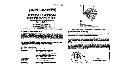
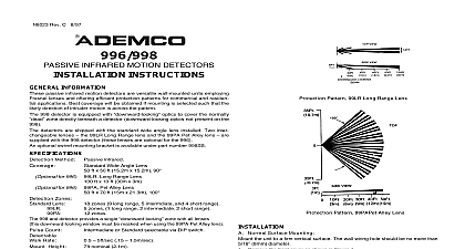
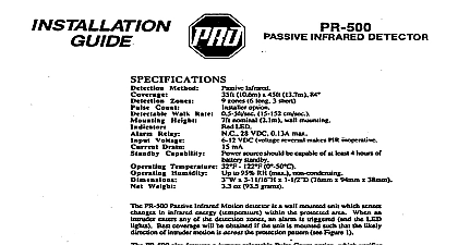
NSS43 7191 passive motion detectors are versatile employing Fresnel and efficient protection patterns for commercial and applications The detectors sense Sudden slight changes temperature within the area Of when an intruder crosses or enters any change in infrared energy Best coverage will be selected such that the likely of intruder motion is across the pattern No 990 is equipped with a wide angle 990LR with a long range a pet alley lens Method the and the No 990PA mounting Infrared 990 wideangk x 17m swm ft x 0.4 n x 2.6m 99OPA ef a fey x 17m Rate Height Voltage Reley Dmln Capability nominal 2 lm LED with enabWdisabte VDC normnat Wtage makes PIR inoperative A N C D 13A max ratmg 28V DC S ohm intefnat resistor in source sh0ukt be standby Humidity Use9zRH 1229 PF 50 Wtie 5lmm Hiah 96.5mm D 3 40.6mrn HINTS screens not install where the defector is exposed to direct or directly above strong sources of heat sure the detection area does nol have ob pieces of fur plants etc which may block the pattern of areas which contain likely to produce a rapid change in tempera such as cenrral heating radiators or ducts or of any kind air conditioners open flame not mount on an unsrable surface a detector Avoid running alarm wiring close to heavy electrical power cables PATTERNS protection patterns shown belo can be modified suit the needs of a particular area by selective use of masking strips supplied AREA No 990 AREA No BQOPA Mounting the unit to a firm venical surface flat on wall or corner The wall wiring hole should be no more than 6 8rnm diameter the front cover as shown in Figure 1 the screw holding the PC board in the base the screw is located at the center of board and temporarily board PC board carefully to Figure 2 Knockout holes in the base are normal surface mounting on a wall or for comer mounting out only those mounting holes required wiring emerging from the wall through the wire slot at the bottom of the detector base sure wires have sufficient sbdr allow the board lo slide up and down freely when the are subsequently connected lo the terminals the board Then mount the base lhe PC board with renninal block dosest the wiring access slot in the base Before fully the holding screw make sure the board positioned the appropriate selling on the scale and Fig 3 to WlRiNG CONNECTIONS before replacing front cover Vertical 1 Cow hmoval Vertical Pattern Adjustment prelection pattern provided by the lens in Use Can raised or lowered by re positioning PC boatd n detector A graduated scale to Ihe right of the see Fig 3 indicates the approximate number of by which the pattern can be raised max l 4 lowered max W The detector is normally shipped the board set to the 0 positlon To make this cover on the detector and the screw holding the PC board the screw is at the approximate center of the board Slide board upward or downward by the number required lhen tighten the holdi again any adjustment you must conduct a walk test 10 proper coverage of the area to bs protected as under Test Procedures Lens Masklng masking strips have been supplied are for application to one or more lens segments prod Y a protection pattern pattern that suits the masking slrips have been provided for each the lens segments on the standard supplied the PIR Simply peel off the appropriate pressure adhesive strip s and apply over the desired segment S Be sure lo affix the masking strips lo inside of the lens not the outer smooth ade the of one zone of protection from the coverage By masking segments of the lens you can lhe coverage lo suit the area lo be prolected or coverage from areas where you anticipate disturbances stabilii heater or other heat producing objecl example CONNECTIONS all wires in through the wire access slot near the bk and conned the screw terminals see 3 for wiring details Beal all openings in the base loam or RTV not supplied prevent drafts or from entering the unit Apply power on y after amfx3cMns haue been made and are pee d protected segment might masked POINT SERVES MARKER FOR 2 Detector Base HERE Igum 3 PC Bosrd Nos B90,990LR and 99OPA I 4 Remote control of LED ENABLE DISABLE delector is shipped wilh the AI I LED dis led enable diible plug in place If desired the LED be enabled atter the Walk Test is oxnplete by ths LED enabteMiie see Fg 3 To the loss of the plug we suggest you install it desired the LED may be aontrofted lmm a remote as foflom Remove the LED enable diie Connect 8 line to the lett hand pin et of the4 two LED 4 Grounding pin 11 wttl able from ground witl enable the LED PROCEDURES Two minute warm up time Is requited after power Testing should be cnndwled with Uw area deared of all people Disarm the system control during the test procedure to repoMg of unwanted alarms TheAIannLEDmustbeenabfedatthistime LED pfug mmoved WIUI lronl cover n place waB through protective observing that the detector LED lights molion is deteued absolute range of all PIR units b subject to because of different types of dothing and ambient temperature For this ensure that the most likely Mnkter routes are within the PIR protectfve zones end that walk is car d out abng these 10 10s the Walk lest is complete the LED may be LED enabf diible plug instaffed PROPER OPERATION order to maintain the detector in proper working should be provided at all times La of 10 en alarm state The units DC soufm have standby power 8wilable for al least 4 of operation during emwgench should never be re rimed or nlocstod the advice of assistance ol the alarm physlcsl surroundings of the protected should not be changed tf lumthue or stock moved or afrMtionii additionof heattng insmad lhe system may haw to be readjjsted should be Conducted hquently weekly by esd deteclor confirm continued proper 1 INTERMITTED