Ademco - 998MX Passive Infrared Detector

File Preview
Click below to download for free
Click below to download for free
File Data
| Name | ademco-998mx-passive-infrared-detector-9837540162.pdf |
|---|---|
| Type | |
| Size | 988.99 KB |
| Downloads |
Text Preview
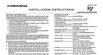
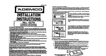
Passive Infrared Detector 998MX Instructions 10 95 Range Normal Mounting the unit to a firm vertical surface The wall wiring hole be no more than 5 16 cid 211 8mm in diameter Remove the front cover as shown in Figure 1 the screw holding down the PC board Refer to Figure 2 For clarity the PC board is not show this diagram Knockout holes cid 210 A cid 211 in the base should used for normal surface mounting on the wall For mounting see section B below Also break out desired wire entry hole at this time holes are X in Fig 2 Feed wiring emerging from the wall through the wire hole near the top of the detector base Make wires have sufficient slack to allow the PC board to up and down freely when the wires are connected the terminals on the board Mount the base Note the orientation of this detector cid 209 wire entry is at top lens at bottom fully tightening the PC board holding screw sure the board is positioned so that the arrow is line with the appropriate setting on the graduated see Table 1 Refer to WIRING CONNECTIONS before replacing front cover Corner Mounting Orient the corner mounting bracket with cid 210 hooks cid 211 point upward See Fig 3 and mount in selected corner 4 screws out the cid 210 release slot cid 211 identified in Fig 2 in the base Failure to do this will make it impossible to the detector after mounting the detector base onto the bracket so that the cid 210 hooks cid 211 are forced through the four self closing in the base see Fig 2 then pull downward to onto the bracket Remove The Detector After Mounting Remove cover and PC board Using blade of small screwdriver push through the slot base of detector press on the release tab in the cor mounting bracket then pull detector upward and from bracket Changing lenses if required Remove front cover upper lens lock located in front cover to upper Fresnel lens support Squeeze lower lock to release lower Fresnel lens support see 4 Note how the lens supports are positions then remove supports Carefully remove the existing lens and replace with optional coverage lens The lens must be with the smooth side facing outward the lens should be oriented with part number on the upper right hand side see 4 Be sure to center the lens Lens surface should be free of dirt foreign and finger prints Use soft dry cloth to wipe surface Replace top and bottom lens supports and then press so that the lens locks with lens snap into Refer to Table 1 for recommended detector pattern for various mounting heights and protection Replace the front cover make sure cover snaps tight Horizontal Adjustment of Lens protection pattern can be moved to the left or right by adjustment as follows Remove the cover inward on the upper and lower lens locks at the or right side only to release the lens supports on side Now slide the lens to the left or right as The lens may be moved as much as 4o from in either direction When the lens is in the desired position press the lens downward on the released side to lock the sup in place Replace the front cover make sure the cover snaps on adjustment conduct a walk test to ensure proper cov of the area to be protected see cid 210 Test Procedures cid 211 Vertical Pattern Adjustment protection pattern can be raised or lowered by re posi the PC board in the detector A graduated scale to the of the board see Fig 5 indicates the approximate of degrees by which the pattern can be raised max or lowered max 20o To make this adjustment the screw holding the PC board Slide the board or downward by the number of degrees required tighten the holding screw again After any adjustment a walk test to ensure proper coverage of the area be protected see cid 210 Test procedures cid 211 Lens Masking supplied masking strips can be used to produce a pro pattern that suits the particular requirements of the area or eliminate coverage from areas where anticipate environmental disturbances that might the PIR cid 213 s stability a heater or other heat producing for example Simply peel off the appropriate pres adhesive strip s and apply over the desired segment s Be sure to affix the masking strips to the of the lens not the outer smooth side Each lens that is masked results in the elimination of one of protection from the coverage pattern standard lens can be used to provide a pet alley To do mask the bottom two rows as shown in Fig 4 and mount though the optional pet alley lens was installed If using the Pet Alley lens or if you have the standard lens to emulate a pet alley lens 1 Removal THE MOUNTING OF THIS WIRE ENTRY AT THE TOP AND LENS AT THE BOTTOM REMOVE COVER INSERT SCREWDRIVER IN GROOVE AND TWIST HOLES SURFACE MOUNTING 3 BREAKOUT RELEASE SLOT WIRE ENTRY 5 OUT FOR CORNER MOUNTING ONLY IN BACK DETECTOR 4 2 Base MOUNTING BRACKET FOR CORNER SCREWS HOOKS 4 MOUNTING BRACKET 4 MOUNTING 4 SLOTS IN BACK OF BASE 3 Corner Mounting 4 Changing Lenses Information passive infrared motion detector is designed for use control panels that support polling loop devices with DIP switches or polling loop devices that their serial number to be cid 210 learned cid 211 It is a versatile unit employing Fresnel lenses and offering protection patterns for commercial and residential Best coverage will be obtained if mounting is such that the likely direction of intruder motion is pattern If the control panel supports Serial No learning you configure the 998MX as a Serial No device see No ID section detector is also equipped with cid 210 downward looking cid 211 to cover the normally cid 210 dead cid 211 zone directly beneath a detector is shipped with the standard wide angle lens but also supports a pet alley lens 998 PA and a range lens 998 LR These lenses are purchased sep An optional swivel mounting bracket is available Method Lens Zones Lens Lenses Infrared Wide Angle Lens x 50ft 15.2m x 15.2m 90o Pet Alley Lens x 70ft 15m x 21.3m 100o Long Range Lens x 10ft 30m x 3m zones 9 long range 5 2 short range 12 zones 5 zones 1 long 2 intermediate 2 short provides one cid 210 downward look zone with all lenses downward look lens must be masked when using the 1 2 or 3 Count Rate Height Voltage Temp 5ft sec 0.15m nominal 2.1m LED with enable disable link peak to peak at polling terminals LED disabled alarm LED enabled source should be capable at least 4 hours of battery 122oF 10o 50oC to 95 RH max W x 4 cid 211 H x 2 cid 211 D max protru 67mm x 111mmx 54mm Pattern Standard Lens Pattern 998 PA Alley Lens must also mask the look down window Connections wires in through the wire access slot at the top of the base near the terminal block and connect to the terminals see fig 5 for wiring terminals Seal all open in the base with foam or RTV not supplied to prevent or insects from entering the unit Apply power only after MOUNTING BRACKET FOR CORNER SCREWS HOOKS 4 After the cid 210 Walk Test cid 211 is complete the LED may be source and detector temperature Check for or gas open ele