Ademco - Aurora Motion Detector

File Preview
Click below to download for free
Click below to download for free
File Data
| Name | ademco-aurora-motion-detector-6349058271.pdf |
|---|---|
| Type | |
| Size | 961.28 KB |
| Downloads |
Text Preview
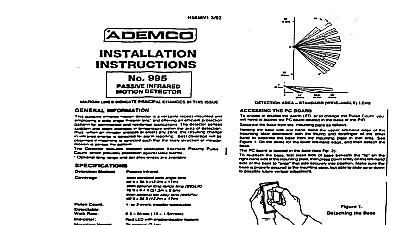
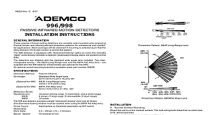
AURORA T AURORA AT INFRARED MOTION DETECTORS 8 99 INSTRUCTIONS VIEW IMMUNE LENS INFORMATION passive infrared motion detectors are versatile wall mounted units Fresnel lenses and offering efficient protection patterns for and residential applications Best coverage will be obtained if is selected such that the likely direction of intruder motion is the pattern installed per the guidelines the Split Zone Optics technology in the Series provides reasonable false alarm protection against pets and animals up to 40 lbs Method Passive Infrared Pet Immune Lens Zones Pet Immune Lens 28 zones ft x 45 ft 10.6m x 13.7m 90 Range Lens optional Part No Aurora LR ft x 10 ft 23m x 3m Range Lens 6 zones Part No Aurora LR over 8 long range 8 intermediate 4 short range Standard or Harsh installer selectable Use Standard for pet immune applications Processing Compensation Advanced dual slope temperature compensation for ambients both above and below body Rate 0.5 10 ft Sec 0.15 3m Sec Height 7.0 ft recommended 2.1m Red LED with enable disable link Relay Form A SPST 90mA 16VDC protective resistor Voltage 8 16VDC Aurora and Aurora T Model Type Aurora AT reversal makes PIR inoperative Alarm w o LED Alarm Standby 4mA 4mA 16mA currents nominal at 12VDC Power source should be capable of at least 4 of battery standby Normally closed with cover on rated at 0.5A Aurora T Aurora AT only Temp 14 122 10 to 50 Up to 95 RH max non condensing 2.9 x 4.1 x 1.5 max protrusion x 104mm x 38mm COUNT POLARITY ZONE CONSISTS OF 2 FIELDS VIEW VIEW RANGE LENS VIEW 1 Protection Patterns Instructions Installations Containing Pets take full advantage of the pet immunity in the Aurora Series the guide below should be followed the center of the detector 7 ft 2.1m high the PIR sensitivity for Standard STD where animals cannot come within six feet of the detector by on furniture boxes or other objects not aim the detector at stairways that can be climbed by animals This unit will provide immunity to false alarms for an individual or a group of animals whose total weight is equal to or less than pounds when the room temperature is above 50 10 optimal pet immunity performance be sure to follow all the guidelines in the section Instructions for Installations Containing Normal Surface Mounting the unit to a firm vertical surface The wall wiring hole should be no than 5 16 8mm in diameter Remove the front cover as shown in Figure 2 Refer to Figure 3 Knockout holes in the base are for normal sur mounting on a wall remove PC board for full access to holes corner mounting see B Corner Mounting Also break out the wire entry hole at this time marked X1 or X2 in Figure 3 Feed wiring emerging from the wall through the wire access hole sure wires have sufficient slack to allow the PC board to be up and down freely when the wires are connected to the termi on the board Mount the base A level may be used on the front case to ensure that unit is vertical see Figure 2 Replace PC board Note the orientation of this detector terminal strip at the bot Make sure the board is positioned to the appropriate setting see 7 Refer to the WIRING CONNECTIONSsection before replacing the cover Corner Mounting holes in the base are used for corner mounting on a Mount in selected corner with 4 screws Replace PC board the mounting orientation of this detector terminal strip at bottom sure the board is positioned to the appropriate setting see 7 Changing Lenses if required Remove front cover Release the lens support frame located in front cover as follows the blade of a small screwdriver between the locking tab and detector case in each of the two corners of the frame and lever tab upward to release See Figure 4 When both corners are remove the lens support frame by lifting and sliding the two corners away from the stops in the front case Remove the existing lens and replace with the replacement lens The must be installed with the smooth side facing outward the lens should be oriented with the notches at the top Be to center the lens with the notches aligned with the protrusions in front case Lens surface should be free of dirt foreign matter and finger Use a clean dry soft cloth to wipe lens surfaces the lens support frame into its original position and then press on the frame so that the lens locking tabs snap into position each of the four corners Replace front cover REMOVE COVER LEVEL AGAINST POINTS TO ENSURE IS VERTICAL INSERT SCREWDRIVER GROOVE AND TWIST 2 Cover Removal PROCESSING LINK ENABLE DISABLE LINK 3 Detector Base 4 Changing Lenses 3 4 6 DETAILS POWER OBSERVE TAMPER LOOP ONLY CLOSED CIRCUIT LOOP 5 Wiring Connections CONNECTIONS all wires in through the wire access hole and connect to the screw see Figure 5 for wiring details Seal any openings in the base foam or RTV not supplied to prevent drafts or insects from entering unit Apply power only after all connections have been made and are ENABLE DISABLE OPTION Figure 3 for location of LED enable disable jumper link enable the LED remove the LED enable disable jumper link To dis the LED replace the jumper link See Figure 6 for proper positioning the link ENABLE DISABLE PROCESSING ENABLE OFF DISABLE ON 6 Selectable Options ON 2 POSTS LINKS ON 2 POSTS PROCESSING OPTION Figure 3 for location of Pulse Processing selection jumper link Pulse Processing INT This is the recommended setting any location where an intruder is expected to cover only a small por of the protected area It tolerates normal environments on this setting NOT recommended for pet immune applications Pulse Processing STD This is the recommended setting for applications It tolerates environmental extremes on this setting STD pulse processing is recommended for pet immune appli NOT recommended for use with the optional Long Range Aurora LR Pulse Processing HARSH This is the recommended setting for severest of environments and should only be used in locations where intruder is expected to cover moderate to large portions of the protect area NOT recommended for use with the optional Long Range Aurora LR PROCEDURES Two minute warm up time is required after applying power should be conducted with the protected area cleared of all people the protective system control during the test procedure to pre reporting of unwanted alarms Remove front cover and set Pulse Processing Option to the setting will be used for this detector in the installation The LED must be at this time see Figure 6 Replace front cover and walk through protective zones observing that detector LED lights whenever motion is detected the LED as a Walk Test indicator during this procedure absolute range of all PIR units is subject to variation because of differ types of clothing backgrounds and ambient temperature For this rea ensure that the most likely intruder routes are well within the PIR pro zones and that Walk Testing is carried out along these routes the Walk Test is complete the LED may be disabled see Figure 6 PROPER OPERATION order to maintain the detector in proper working condition it is impor that the user observe the following guidelines P