Ademco - Lynx Quick Start Guide

File Preview
Click below to download for free
Click below to download for free
File Data
| Name | ademco-lynx-quick-start-guide-5930467218.pdf |
|---|---|
| Type | |
| Size | 1.04 MB |
| Downloads |
Text Preview
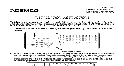
10 98 Quick Start Guide can help you install the LYNX quickly and easily by providing the basic for installation using the built in defaults For more detailed information and important refer to the LYNX Installation Instructions following steps assume that one of the system default tables will be used programming data values and Powerline Carrier Devices other than those listed in the default see the Installation Instructions 3 door door detector detector 2 door door detector detector door door detector 3 arm away 2 disarm 4 close device 1 1 restore device 1 3 arm away 2 disarm 4 close device 1 1 restore device 1 Table Summary Table 1 zones 26 33 are RF button zones and programmed the same as in Table 1 alarm alarm alarm 4 door door detector detector alarm 5 door door detector alarm Program Mode installer code 8 0 0 Mode Zone Programming Sequential Mode Assign Zone Voice Descriptors to Program characteristics report codes and serial numbers Series transmitter serial numbers descriptors for each zone Program Mode 99 allows re entry into the Program mode using Installer Code 8 0 0 inhibits re entry into the Programming mode using the Installer Code Tables 2 and 4 support the automatic paging feature open close events reported to pager phone and a Powerline Carrier Device programmed as device 8 which closes and stays closed upon alarms and restores after bell timeout For other applications or actions e g using a pulsing see the 80 Powerline Carrier Device Programming section of the Installation Instructions Primary report format for all tables is Ademco Contact ID reporting Tables 2 and 4 also use Contact ID secondary reporting Tables 1 3 and 5 use 4 1 format for secondary reporting Tables 1 and 5 record all events in the event log Tables 2 3 and 4 record only alarms alarm restores and trouble restores in their event logs to Installing LYNX Separate the front assembly from the back plate and mount the back plate NOT disconnect the ribbon cable from the terminal strip board Disconnect the cable only from the front board Make wiring connections as follows the incoming phone line to either the 8 position jack or terminals 2 TIP and 3 RING the handset phone lines to either the RJ11 jack or terminals 4 TIP and 5 RING For full line seize operation see the installation instructions used connect a piezo sounder to terminals 10 and 11 used connect a bell to terminals 11 and 12 using Powerline Carrier Devices connect com data sync lines from the PL513 Powerline Interface to terminals 9 13 and 14 respectively Powerline Carrier Devices according to their instructions wires from the 1332 1332CN AC Transformer to terminals 15 and 16 After all wiring connections are made carefully reconnect the ribbon cable to the front assembly board connector properly aligning the red wire then snap the front assembly to the back plate so is held by the locking tabs the transformer into a 24 hour 110VAC unswitched outlet out the battery drawer and install either a single 9V alkaline battery or six 1.5V alkaline Use only nonrechargeable alkaline batteries installing the battery ies slide the battery drawer into the back plate only after AC power has applied Set a programming default Programming mode Installer Code 8 0 0 97 then press a number 1 5 to select a default table from the tables listed on page 1 Program the variable data fields 24 RF House ID then enter the desired 2 digit RF House ID for wireless keypads 40 PABX Code if used then enter up to 6 digits If fewer than 6 digits are used press to the field and advance to the next field 41 Primary Phone Number then enter the primary phone number up to 20 digits If fewer than digits are used press to end the field and advance to the next field 42 Secondary Phone Number if used then enter the secondary phone number up to 24 digits fewer than 24 digits are used press to end the field and advance to the next field 43 Primary Account Number then enter the primary account number If only 3 digits are used to end the field and advance to the next field 44 Secondary Account Number if used then enter the secondary account number If only 3 are used press to end the field and advance to the next field 88 Pager Characters if using Default Table 2 or 4 then enter up to 16 digits which may be by your pager service e g account number PIN etc If fewer than 16 digits are used press to end the field and advance to the next field 94 Download Phone Number then enter the downloading computer phone number up to 20 If fewer than 20 digits are used press to end the field Enroll transmitter serial numbers by pressing 83 while in Programming mode then follow the prompts cid 4 cid 4 cid 20 cid 22 the 2 digit zone number of the first transmitter whose serial number you are entering press The system displays the prompt the 7 digit serial number printed on the transmitter If you enter an incorrect digit the key to back up to that digit and reenter the correct digit When all 7 digits are press the key Review the displayed serial number If correct press again to it The next zone number to be enrolled will display at the prompt for 30 seconds If is the desired zone number enter its serial number as described above If not either 30 seconds or press the key to display the prompt system automatically displays the next zone number for which a serial number may be Press 1 to return to the prompt described above to enroll this zone the zone number displayed is not desired press 0 to return to the prompt where you then enter a different zone number all serial numbers have been enrolled return to the prompt then enter 00 to exit enrollment blinking Press 99 to exit Program mode 2 Set RF House ID in the wireless keypads as follows using a 5827 wireless keypad set the keypad DIP switches to the RF House ID programmed in 24 If using a 5804BD button key or 5827BD keypad set the RF House ID per its instructions using Powerline Carrier Devices set their House ID to programmed as or use field 25 to the ID to avoid conflicts with existing installations Set the Real Time Clock as follows time date setting mode by entering the Installer Code 63 hour prompt is displayed Enter the correct hour then press to accept and advance each subsequent prompt enter the correct value then press will exit this mode automatically after entering the year or if no keys are pressed for 1 minute Test the system as follows installation and programming enter Installer Code 5 exit Test mode enter Installer Code OFF Assign desired User Codes by following the procedures on the next page and in the User Guide the user how to perform the various system functions Perform site initiated downloader session to load central station ID by Installer Code 1 PREVENT OF AT TELCO BEFORE UNIT OUTPUT CIRCUITS POWER LIMITED HANDSET SOUNDER JUMPER DISABLE EQUIPMENT SHOULD BE INSTALLED ACCORDANCE WITH THE