Ademco - Quest 2000 Microwave-PIR Intrusion Detector

File Preview
Click below to download for free
Click below to download for free
File Data
| Name | ademco-quest-2000-microwave-pir-intrusion-detector-8412706935.pdf |
|---|---|
| Type | |
| Size | 1.21 MB |
| Downloads |
Text Preview
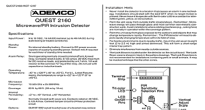
INSTALLATION INSTF UCTIONS Rev B 11 95 2000 Image Processing Detector microwava detection pattern shown in Diagram 1 coverage in open space practical applica when the detector ia bounded by ceiling floor and reflections occur and the device provides volumetdc detector responds to changes in energy which occur an irbtrudarmoves into the combined protection pat Best t ovarage will ba obtainad if tha mounting site is so that the likely direction of intruder motion is tcross the pattern and angles slightly toward the see Magram 1 Mounting m addition Ademco INFORMATION has taken the next step on motion detector with the QUEST detector QUEST 2000 is a detector which uses a diverse methods of detection to of false alarm immunity The passive provides 22 zones of wide angle coverage with a of 40 feet is a zone that provides protection in the area close to mounting wall A microwave detector provides alarm PI R optical system divides the area into a seties of zones A dual element PIR sensor measures the of infrared energy in each zone The microwave provides a volumetric coverage pattern When an enters the combined PIRlmicrowave protective PIR and microwave signals will be generated at same time and the detector relay will repofi an alarm QUEST 2000 includes a microprocessor with analog conversion which provides Dual processing for immunity to disturbances and reduced false alarms Ademco image processing of 256 different environ contrition levels Adaptive microwave signal processing for false alarm 40 ft 12m x 50 ft 15m range with zone Adjustable microwave range with potentiometer Rejection with digital notch filter of fluorescent Trouble output Unit pedorms self test and repotis a Unit continues to operate as PIR only Alarm LED local and remote disable Dgital pulse count and pulse recognition provides false immunity in harsh environments True digital temperature comp6nsafion DIP switch selectable functions walk test Pulse Count PIR Alarm LED disable Ademco ACCU TRAK test additional conventional Dust etement pyroatactric PIR sensor and Fresnel are included design Does not require any optics Superior Low current drain which allows for extended power standby batte life 12VDC operation Wall and cornar mounting brackat providad Optional swival bracket is availabla AND LOCATION CONSIDERATIONS protective pattarns are shown in Diagram 1 for nominal mounting height of 7.5ft 2.3m 1 PROTECTION PA ERN false alarm be detector but the following racommendafions remarkably I mounting haight approximately the floor not nlount on an unstable sutiace Locate the unit on sturdy inside wall whenever possible Avoid sources of such as loose fitting doors and walls that shaka heaq traffic exists not install on or close to metal structures such as door framas shelves ate not include space haatars in the protective pattern possibla to avoid rapid temperature changes vib sfion from fans Avoid aiming directly at a fluorescent light Keep at Ieaat m away from them if possible They present reflections to the microwave aeneor Microwave penetrate kept at as low a sening as possible building metal which reflacts transmission objects outside of the protected area may be detected unless the microwave sensitivity mini penetration have cutiains screens pieces of furniture etc which may block the PIR portion of the pattern Make Avoid running alarm wiring close to heavy duty power cables Remove front cover by twisting a screwdriver blade in groove between cover and base at the location in Diagram 2 and then bffingthe cover off Mount wall plata to a firm vertical surface flat on wall in corner Position the plate ao that field wiring is in the hole at the top of the plate wall wiring no larger 3 diameter 5 16 Feed wiring through the wiring hole in the bracket and the wiring trough at the rear of the base through the hole in the base Do not connect terminal yet Attach unit to wall plata by engaging all four hooks on plate into slots on the rear of the base and by the unit downward See Diagram 3 The unit is locked to the wall plate by a plastic tab in the plate that engages an opening in housing base sea Diagram 3 The unit can be removed from the plata by removing the depressing the tab via a hole in the base a small blade screwdriver and then stiding the upward see Diagram 4 you of the wall plate provided is recommended nOt to use the wall plate knockout holes for direct or corner mounting are provided in the unit base to access to them circuit board must be carefully from the base by bending back the circuit board tab at the Iowar edge of the board Do not use the plate keyholes for direct mounting use the holes above the Ckeyholes to the left and of the for corner mount mIST scRNDRY R BMDEINGROOvE COVEROFF 2 COVER REMOVAL HOLES 3 4 3 WALL PLATE Diagram 4 Ccmnactions all wires through the unifs wiring ent near block and make connections 4 and in the table below indicated in Vlnput Powar muat be provided a 12VDC filtered source with 25mA 4 hours of standby w caoacitv at Supply ground Contacts N C open on alarm to closed protective circuit LED Remote Disable indication Same assening DIP 3 UP Output Upon aupewision failure this collector output will go low requires pull up resistor Useahielded wire UL installations both LEDs will flash to annunciate The detector continues to operate as only Selections SENSITIVIW CONTROL the Potentiometer clockwise to increase sensitivity SWITCH S lNGS UP for Walk Teat selection relay will remain open Test is eelected UP for setting Pulse Count to 3 UR foralarm LED daable indication UNUSED Wait at Iaast two minutes after applying power attempting to walk test unit the walk testing of the detector with the protected do ttis afler business ia closed The protective system control be disarmed during the procedure prevant unwanted alarms may be more convenient come REMOEDISABLEWEN 7WC APPLIEW OUP SHIELDED WIRE FOR UL lNSTALMn S SUPERWSlON CIRCU BOARD REPUCINGm ENmY HOE WIRING CWNEL BEE 12 lNP REL SEUN T 00ARO HOLDING TAB WCK IF NECEWRY REMOE BOARD MICROWAE CLOCWISE M D CTOR LED BELOW LED BELOW INDICATIONS UP Red and Green LEDs on for approx 90 sem FAILURE Red and Green LEDs flasfdng Red LED on TEST when selectedvia DIP switoh l LED flashesfor microwave LED flashesfor PIR When Walk Testis selected alarm relay is constantly held to prevent leaving the detec r the walk test mode 4 INTERIOR OF DETECTOR the two LEDs PIR information below As you enter Walk Test unique