Ademco - Quest 2120 Microwave-PIR Intrusion Detector

File Preview
Click below to download for free
Click below to download for free
File Data
| Name | ademco-quest-2120-microwave-pir-intrusion-detector-6510974283.pdf |
|---|---|
| Type | |
| Size | 1.06 MB |
| Downloads |
Text Preview
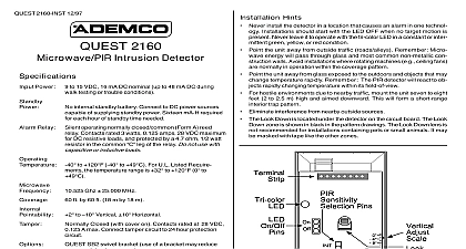
QUEST 2120 INST 12 97 2120 Detector Power to 15 VDC 16 mA DC nominal up to 48 mA DC walk testing or trouble conditions Power No internal standby battery Connect to DC power capable of supplying standby power Sixteen required for each hour of standby time needed Relay operating Normally Closed reed relay Contacts 3 watts 125 mA 28 VDC maximum for DC re loads and protected by a 4.7 ohm 1 2 watt in the common leg of the relay Do not use capacitive or inductive loads to 120 40 to 49 For U L Listed Re the temperature range is 32 to 120 to 49 Ghz 25 MHz ft by 20 ft 10.7 m by 10.7 m to Vertical Horizontal Closed with cover on Contacts rated at VDC 0.125 A max Connect tamper circuit to 24 protection circuit SB2 swivel bracket Use of a bracket may range and dead zone area protected coverage area is where the microwave and PIR overlap use the optional Look Down Zone the Mask must be from the Look Down Lens See Figure 2 the black mask only Do not attempt to remove white lens assembly Do not remove the mask for pet Hints Never install the detector in an environment that causes an alarm con in one technology Good installations start with the LED OFF there is no target motion It should never be left to operate with tri color LED in a constant or intermittent green yellow or red con Point the unit away from outside traffic roads alleys Remember Mi energy will pass through glass and most common non metal construction walls Avoid installations where rotating machines e g fans are normally in operation within the coverage pattern Point the unit away from glass exposed to the outdoors and objects may change temperature rapidly Remember The PIR detector react to objects rapidly changing temperature within its field of Eliminate interference from nearby outside sources Instructions Installations Containing Pets QUEST 2120 will provide reasonable protection from nuisance caused by the following sources A dog up to 100 pounds Two dogs up to 60 pounds each Up to 10 cats Multiple small rodents such as rats Random flying birds take full advantage of the QUEST 2120 Pet Exclusion Technology following guidelines should be followed Mount the center of the detector 6 1 2 feet high and adjust the vertical to 9 Set the PIR sensitivity for standard STD Mount where animals cannot come within six feet of the detector by on furniture boxes or other objects Do not aim the detector at stairways that can be climbed by an animal Adjust the microwave range for the minimum acceptable coverage for room in which the detector is installed Never install with the micro range exceeding 20 feet nuisance protection has not been verified by Underwriter Inc 1 Coverage Pattern 2 Interior View Select a location likely to intercept an intruder moving across the cov pattern The surface should be solid and vibration free Mounting range is six to eight ft 1.8 to 2.4 m Recommended mounting is 6 1 2 ft 2 m Remove the cover Insert a flathead screwdriver into the locking tab at the bottom front of the detector Pull the cover up and forward Remove the circuit board from the base Loosen the Vertical Adjust screw and slide the circuit board down then out Using the base as a template mark the location of the holes on the surface Route wiring unpowered as necessary Route to the rear of the base through the wire entrance Firmly mount the base to the mounting surface Return the circuit board the base and tighten the Vertical Adjust Screw power after all connections have been made and Do not coil excess wiring inside the detector Terminals 1 2 Power are 9VDC to 15VDC Use smaller than 22 AWG wire 500 feet 150m max be the detector and the power Terminals 3 4 Alarm relay contacts rated at three 0.125 amps 28VDC maxi for DC resistive loads and by a 4.7 ohm 1 2 watt Do not use with capacitive or inductive loads Terminals 5 8 Spare Terminals 6 7 Tamper contacts rated at 28VDC 0.125A Plug the wire entrance hole with the foam plug provided Operation the detector experiences a Microwave or PIR self test failure four sequence it is in need of replacement walk testing the LED will light for the first technology microwave PIR and then light red to indicate a detector alarm The LED will not activation of the second technology by lighting its color Page 2 Selection On Off pins The ON allows operation of tri color LED If the tri LED indication is not after the setup and tests have been place the plug in OFF position OFF position does not prevent the tri color LED from a supervision trouble condition Sensitivity Selection Pins Selection of the PIR response may be selected by placing the plug across the pins marked for standard or INT for intermediate mode Sensitivity The recommended setting for maximum false immunity It tolerates environment extremes on this setting setting is required for pet avoidance Sensitivity The recommended setting for any location an intruder is expected to cover only a small portion of the area It tolerates normal environments on this setting This will improve your intruder catch performance Intermediate is not recommended for installations containing pets and Walk Tests the vertical starting angle from the chart below the vertical starting angle for the mounting height and range proper vertical angle must be for installations pets Place the LED plug in the ON position and the cover Wait at least two minutes after applying before starting walk tests During the warm up period the tri color LED will flash red until unit has stabilized and has seen no movement for two approximately one to two minutes When the LED flashing the detector is ready to be tested With no in the protection area the LED should be OFF If the is on re check the protection area for disturbances the microwave yellow or PIR green technologies Turn the Microwave range adjust to minimum Walk test across the pattern at its farthest edge then several times to the detector Start walking from outside of the intended pro area and observe the tri color LED The edge of the pattern is by the first green PIR activation of the LED or the first red if the yellow microwave LED activates first Walk test from the opposite direction to determine both boundaries center of the pattern should be pointed toward the center of the protection area Slowly bring your arm up and into the pattern to mark the lower bound on PIR alarm Perform this task at 10 to 15 ft 3.1 to 6.1 m from the Repeat from above for the upper boundary The center of the should not be tilted upward desired coverage can not be achieved try angling the coverage up or down to assure the pattern is not aimed too high or low pet applications do not adjust below recommended angle detector uses a tri color LED to indicate the various alarm and troubles that may exist See chart below PIR Pattern Coverage angle of the PIR pattern may be vertically positioned between and 2 by loosening the Vertical Adjust screw and sliding the board up or down Moving the board up will angle the downward Tighten the screw snug when positioning is pattern may be moved horizontally by moving the to the left or right Microwave Coverage is important to wait one minute after removing replacing the so the microwave portion of the detector can settle and wait at least 10 seconds between the following walk testing The tri color LED should be OFF before walk testing Walk test across the pattern at the intended coverage farthest end