Ademco - RX360SN Ceiling Mount Multiplex Passive Infrared Detector

File Preview
Click below to download for free
Click below to download for free
File Data
| Name | ademco-rx360sn-ceiling-mount-multiplex-passive-infrared-detector-0234165789.pdf |
|---|---|
| Type | |
| Size | 1.08 MB |
| Downloads |
Text Preview
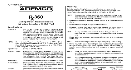
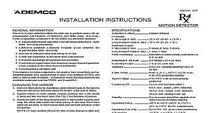
RX360SN INST 12 97 Mount Multiplex Passive Infrared Detector with Self Test by 60 ft 18.3 m diameter coverage when on 8 to 18 ft 2.4 to 5.5 m high ceilings consists of 64 zones grouped into 16 barriers one additional zone looking straight down from unit sabotage Each barrier is 30 ft 9.2 m long 4.4 ft 1.3 m wide at 30 ft 9.2 m Choice of two modules depending on ceiling height For U L Listed Requirements the coverage is 360 by 54 ft m when mounted from 10 to 13 ft 3.1 to 4.0 m using AR8 13 Array and when mounted from 15 to 18 ft 4.6 to m using the AR13 18 Array Power by polling loop selectable for Standard or Intermediate storage and operating range is 20 to 120 to 50 For U L Listed Requirements the is 32 to 120 0 to 50 a location likely to intercept an intruder moving across the pattern See Typical Placements to Achieve Coverage The mounting height is 8 to 18 ft 2.4 to 5.5 m mounting surface should be solid and vibration free e g tiles should be secured if the area above the tiles is used an air return for HVAC systems Do not mount near air handling system outlets or in areas of extreme Remove the cover by turning it counterclockwise Remove the base from the enclosure by pressing the two enclosure tabs inward while lifting the enclosure away from the base rock the enclosure side to side during removal to the friction caused by the base to enclosure terminal Route wiring as necessary to the rear of the base and through the hole sure all wiring is unpowered de energized before routing Firmly mount the base Depending on local regulations the base may directly surface mounted using anchors mollies or wing nuts or be mounted to standard four inch octagonal or square electrical RX360SN base will not completely cover a four inch square Where aesthetics are important a four inch octagonal box recommended to removable ceiling tiles is not recommended unless sandwich is made of the base ceiling tile and a back plate the tile Covers used for four inch octagonal and square make a suitable back plate when used with bolts and nuts as an example the Optical Module AR8 13 or AR13 18 Replace the enclosure onto the base For ceilings between 8 and 13 ft 2.4 and 4.0 m from the floor use the module marked AR8 13 This marking can be found next to the optical module tabs For ceilings between 13 and 18 ft 4.0 and 5.5 m high use the optical marked AR13 18 To replace an optical module push the optical module tabs towards the until the module snaps free of the circuit board Holding the new by the tabs snap the new module into place Avoid fingerprints on the mirrored surfaces Should the mirrored sur become soiled or otherwise marked they can be cleaned using a clean cloth and any commonly available mild window cleaner 1 Coverage Pattern 2 Internal View APPLY POWER AFTER ALL CONNECTIONS BEEN MADE AND INSPECTED Do not coil excess wiring inside unit must be observed Improper connection may cause the bus to malfunction Terminals 1 2 the detector to multiplex bus wire the T strip as above Switch Settings RX360SN has several that are controlled the configuration Mode S1 modes depend on the type of coverage desired and the environment Standard Sensitivity Tolerates environment extremes on this setting requires the largest amount of intruder motion to achieve an alarm detector is shipped in Standard Sensitivity mode Sensitivity The recommended setting for most installa Use in locations where an intruder is expected to cover only a portion of the protected area Tolerates normal environments on setting Although the sensitivity modes provide different degrees of to environmentally caused alarms the installer should peak background noise voltage readings do not exceed VDC Timer S2 and S3 switches S2 and S3 for the desired anti blocking timer time To 3 or 30 days put its switch in the ON position If both switches are the anti blocking timer defaults to 30 days The detector is with the anti blocking timer disabled No ID unit does not utilize DIP switches to set its zone number ID Each has a unique factory assigned serial number which must be by the control panel during the zone programming procedure this PIR can be used only with a control panel that supports number devices that this PIR unique factory assigned serial number can be found the bar code label on the left hand corner of the PC board PIR serial number can be entered by one of the following Downloading Zone Definition screen of V Link software Recom for large installations and installations where foot traffic can be controlled Entered in manually at the learn prompt during manual zone pro see Important below Learned by faulting the detector twice while at the learn prompt dur manual zone programming programmed manually be sure that other polling loop sensors are not so that they cannot send a signal to the control while this PIR being programmed mask PIRs don open close doors etc To be sure that other polling loop devices are not activated entering serial numbers manually power the system down the polling loop at the control power back up again and enter the program mode Then proceed to Step 1 below to reconnect the polling loop when programming is com powering the system down first either manually enter or learn the unit serial number Enter 93 Zone Programming mode Enter the Response Type and other zone information for the PIR press to advance from prompt to prompt At the Input Type prompt enter 6 for SL Serial Polling Device and At the Learn S N prompt enter Y es At the Input S N prompt either enter the serial number manually and 1 for the loop number or fault the PIR being learned the keypad beep to confirm signal Wait three to six seconds and fault the again the keypad should beep again to confirm The PIR should be learned A 1 should appear under the L on the zone sum screen If an N is displayed the PIR has not been learned Jumper Press to continue programming zones detector is shipped with this jumper in the BUS more information see the Zone Programming section of the control installation instructions During normal operation this jumper should be in the BUS operation For walk testing or location testing the detector can be temporarily on 6 to 15VDC source When operating from a DC source jumper should be in the DC position This will cause the LED to the detector alarm state and Walk Testing Attach test leads to the Noise Voltage terminals The outside terminals common and the center terminal is positive Place the cover on the unit and twist lock it clockwise into place Gain RX360SN permits selection of the signal gain upon the environment to be protected The select jumper is located under the optical module High Gain Recommended for large coverage applications up to 60 ft m in diameter The RX360SN is shipped in this setting If the gain jumper is missing the unit will default to High Gain Gain Recommended for applications where the area to be cov is 40 ft 12.2 m or less in diameter and for applications where Gain may be too sensitive for environmental extremes the RX360SN for Low Gain reduces the coverage area 40 ft 12.2 m in diameter sure the test leads are dressed the cutout Apply power to the unit Wait at least two minutes after applying power start walk tests Walk testing should be done across the pattern as shown The edge of the coverage pattern is determined the Alarm Test LED indicator first turns on Walk test the unit from all directions to deter the boundaries 2 Tests Measurement anti blocking timer time period may be set for 3 to 30 days This may also be disabled by setting the anti blocking timer configu switches S2 and