Ademco - RX4GLD Passive Infrared Detector

File Preview
Click below to download for free
Click below to download for free
File Data
| Name | ademco-rx4gld-passive-infrared-detector-0247986135.pdf |
|---|---|
| Type | |
| Size | 995.65 KB |
| Downloads |
Text Preview
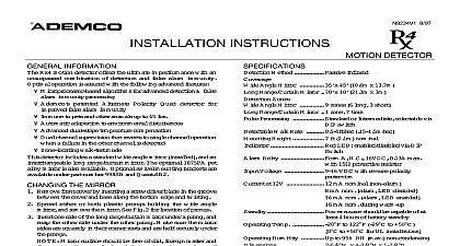
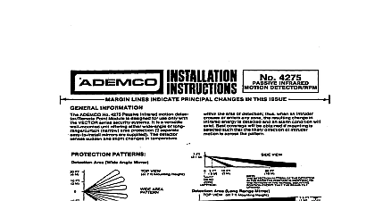
INSTRUCTIONS 8 97 DETECTOR INFORMATION Rx4GLD motion detector offers the ultimate in performance with unsurpassed combination of detection and false alarm immunity operation is assured with the following advanced features algorithms for advanced detection false immunity processing patented Alternate Polarity Quad detector for false alarm immunity to pets and other animals up to 45 lbs adaptation to environmental disturbances sensitivity walk rate 10ft sec dual slope temperature compensation channel supervision that reverts to single channel operation a failure in the other channel is detected C relay and tamper walk test mode detector includes a standard wide angle mirror installed and an long range curtain mirror The optional 1875PA pet mirror is also available Optional swivel mounting brackets are under part number 998SB and Quest SB2 THE MIRROR front cover by inserting a screwdriver blade in the groove the cover and base along the bottom edge and twisting either or both plastic prongs holding the wide angle and remove the mirror See Fig 2 for location of prongs one side of the long range curtain mirror under a prong and the other side under the other prong Make sure the mirror are squarely in their corner rests and are held securely under prongs Mirror surface should be free of dirt foreign matter and Use a soft dry cloth to wipe mirror surfaces if MASKING the supplied masking strips to produce a protection pattern that the particular requirements of the protected area or to eliminate from areas where you anticipate environmental disturbances might reduce the PIR stability a heater or other heat producing for example peel off the appropriate pressure sensitive strip s and apply the desired mirror segment s Each masked segment eliminates zone of protection from the coverage pattern For convenience masking material may be placed on the white filter material the upper tier instead of placing it on the mirror itself VIEW 7 ft 2.1m Mounting Height Method Angle Mirror Range Curtain Mirror 70 x 10 21.3m x 3m Zones Angle Mirror Range Curtain Mirror 1 zone 7 tiers Processing x 45 10.6m x 13.7m zones 6 long 3 short Walk Rate Height Intermediate And Normal sensitivity both selectable via switch ft 2.1m nominal LED enabled disabled via DIP Relay C 16VDC 0.13A max with 15W Voltage VDC with reverse polarity at 12V mA nominal non alarm resistor source should be capable of at mA nom alarm LED disabled mA nom alarm LED enabled mA nom during warm up 4 hours of battery standby to 122 cid 176 F 29 cid 176 C to 50 cid 176 C to 50 cid 176 C for UL installations Temp Humidity to 95 RH max non condensing x 4 3 8 H x 1 7 8 D x 111mm x 48mm NOTE The segment opposite the zone to be eliminated the correct one to mask For example to eliminate the rightmost mask the leftmost mirror segment PATTERNS 1 shows protective patterns for a nominal mounting height of ft 2.1m coverage will be obtained when the mounting site is selected so the likely direction of the intruder is across the pattern of the ft ft ft ft AREA PATTERN PATTERN VIEW ft VIEW at 7 ft 2.1m Mounting Height VIEW ft ft ft ft ft ft ft ft ft ft ft ft ft DETECTION PATTERN OF THE IN THE INVERTED POSITION IDENTICAL TO THE PATTERN IN THE MOUNTING POSITION EXCEPT THE BEAMS TILT UPWARD 1 Coverage Patterns PET IMMUNITY Rx4GLD provides reasonable protection from nuisance alarms by pets or animals up to 45 pounds if the following guidelines followed Mount the center of the detector at 7 feet high Set the sensitivity to Standard STD and Normal Mount where animals cannot come within 6 feet of the detector climbing on furniture boxes or other objects Do not aim the detector at stairways that can be climbed by the OR CORNER MOUNTING the unit to a firm vertical surface The wall wiring hole should no more than 5 16 8mm diameter Remove the front cover and PC board Referring to Figure 2 break out the desired knockout mounting Use knockout holes A for normal surface mounting Use holes B for corner mounting Break out the desired entry hole marked X1 or X2 at the top of the detector base Feed wiring emerging from the wall through the wire access hole Mount the base and reinstall the PC board Refer to WIRING CONNECTIONS section before replacing the CEILING MOUNTING versatility of this detector permits optional ceiling mounting the Long Range Curtain mirror This provides a 15 20ft 4.5 forward looking curtain pattern as shown in Figure 3 The procedure is the same as for Normal Wall Mounting that the unit is ceiling mounted with the unit facing toward detection area CONNECTIONS Bring all wires through the wire access slot at the top of the base near the terminal block and connect to the screw See Figure 4 for terminal designations Seal any openings in the base with foam or RTV not supplied to drafts and insects from entering the unit Apply power only after all connections have been made and SWITCH SETTINGS the DIP switch to select Walk Test Normal mode and Pulse options Use a small pointed tool to move the switch OFF or ON as desired Walk Test Mode DIP position 1 Normal Mode Walk Test Mode See TEST PROCEDURES section for Processing Option DIP position 2 Pulse Processing setting for maximum false alarm It tolerates environmental extremes on this Pulse Processing setting for locations where an intruder is to cover only a small portion of the protected It tolerates normal environments on this setting this setting with the Long Range Curtain mirror Enable Disable Option DIP position 3 the LED Disable the LED screwdriver this end to open 2 Back Case with Mirror unit so that window is towards area 12 ft 3 Detection Area with Ceiling Mounted Using Long Range Curtain Mirror C Switch 4 Wiring Details Processing Processing Operation Enabled Sensitivity Mode Disabled Sensitivity Option DIP position 4 Normal Sensitivity High Sensitivity setting for maximum false alarm Maximum environmental extremes are on this setting setting when ambient temperature is to approach the temperature of the human body 90 cid 176 F 32 cid 176 C 5 DIP Switch Functions 2 detector provides advanced dual channel supervision and a output terminal If a failure is isolated to only one of the two channels the detector will continue to operate as a dual element Continued single channel operation can be verified by walk with the LED enable Even though some operation is the unit should be replaced as soon as poss