Ademco - Ultrasonic Motion Detectors Installation Addendum

File Preview
Click below to download for free
Click below to download for free
File Data
| Name | ademco-ultrasonic-motion-detectors-installation-addendum-6190327458.pdf |
|---|---|
| Type | |
| Size | 1.02 MB |
| Downloads |
Text Preview
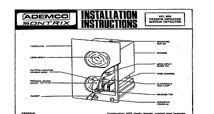
ADDENDUM TO INSTALLATION INSTRUCTIONS MOTION DETECTORS SOURCES OF SWITCHED CONTROL VOLTAGE SIGNAL FOR OPERATING MODES attach diagram should be substituted for Diagram 5 in the accompanying installation instructions It has been to include information for nawer controls and also contains Changed information relating to Nos 4080 and Alarm LogiCenters that AC powered detectors Nos 450,464,750,764,760,764 may obtain DC control signals from 12 wit controls wall as from 6 volt controls PROCESSING 1021 1000 1024 I Nos 33K THRU S lK OHM MIN OTHER ANY UNUSED LEAD SAME TERM AS BLACK OF No 688 RESISTOR ANY VALUE FROM 2 THRU OHM W MIN m SEE OTHER SIDE 3183 DEVICE MANUFACTURING owsto of Pmw v cowownw Eileen Way Syosset New York 11791 4 ALARM R WHITE OTHER ANY SAME TERM No 666 12 OTHER ANY 12V WHILE ARMED WHILE DISARMED ORANGE WITH 4060 12 406OEU VIOLET WITH OTHER SHOWN 1000,1003,1005,1020 These controls may be used provide DC power as well for 6 type detectors only a power source such as a No 492 or 493 or 487 6r 488 type Power Stipply is used for the control 1026,1028 These controls may not be used to provide 6V DC pow for detectors Mepamte source such as a No 492 or 493 or 487 or 488 type Power SuppI would be required for detector powfx 4060 SOSOXL 408042,408OEU Terminal 04 output is a dosing supplementary output trigger 6V which is at arming time only subsequently the opening anc losing of the entry exit delay door 5 TYPICAL SOURCES OF SWlTCHED CONTROL VOLTAGE SIGNAL FOR OPTIONS