Andover Controls ACC EMX 155 Installation Guide

File Preview
Click below to download for free
Click below to download for free
File Data
| Name | andover-controls-acc-emx-155-installation-guide-5297106438.pdf |
|---|---|
| Type | |
| Size | 944.46 KB |
| Downloads |
Text Preview
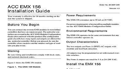
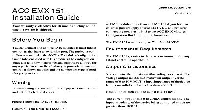
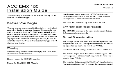
Click for EMX Menu No 30 3001 201 1.2 EMX 155 Guide warranty is effective for 18 months starting on the the system is shipped You Begin can connect one or more EMX modules to most Infinet that have an expansion port The particular con are covered in the ACC EMX Modules Configuration also enclosed with this product The configuration also tells how many inputs and outputs are allowed for particular controller Before you proceed be sure the allows modules and the number and type of mod you plan to use sure wiring and installations comply with local state national electrical codes 1 shows the EMX 155 module 1 The EMX 155 Module A ON B EMX 155 module is approximately 6.13 4.88 1.82 in Requirements EMX 155 consumes up to 42 mA at 24 VDC power requirements when installing multiple modules the ACC EMX Modules Configuration Guide Requirements EMX 155 operates in the same environment that any controller operates in Characteristics two outputs are Form C SPDT they also have pulse modulation PWM PWM allows you to modulate and dampers to 0.1 sec resolution outputs may be programmed or set with manual over switches Form C outputs are rated for 5 A at 24 VAC the EMX 155 Unpack careful when unpacking the unit or units to not damage packaging material must reuse it if you ship the back for repair Connect to the Infinet Controller the module to the Infinet controller as follows sure you disconnect the Infinet controller AC power before you connect any modules at the bottom panel of your Infinet controller On panel is an expansion port in approximately the of the panel at the EMX 155 module Notice that it has a on the top and on the bottom Plug the top into the Infinet controller you are connecting more than one EMX 155 module your Infinet controller connect the second one to the of the first Manuals Online 1992 Andover Controls Corporation 300 Brickstone Square Andover MA 01810 All Rights Reserved for EMX Menu the BOARD switch upper right to 1 on the first 155 and the BOARD switch to 2 on the second 155 If you do not plan to connect more than one 155 module set the BOARD switch to 1 set two modules of the same model number to the board number Connect the External Power Supply necessary you are installing multiple modules you may need an power supply To determine what you need refer the ACC EMX Modules Configuration Guide 2 shows where you connect the external power supply the 2 pin Berg type connector on the EMX 155 Reposition Jumper of One Module Berg type connector immediately to the left of the ex power supply connection has a jumper that you to indicate you are using external power need to change the jumper position only on the mod actually connected to an external power supply Never the jumper position of other modules 3 Jumper Positions for Internal and External Supplies Position Power Position Power is set to the internal position when you receive it shown in Figure 4 you change the jumper position on module connected to the external power supply the Outputs wire the outputs as follows 2 Location of External Power Connection External Power Supply Jumper the appropriate wire under the NC screw and the screw down on it the appropriate wire under the C screw and tighten screw down on it A B ON the appropriate wire under the NO screw and the screw down on it 5 illustrates the wiring for Form C outputs 4 Wiring Diagram for Form C Outputs 3 shows the jumper in the two possible positions one the internal power supply the other for the external Move jumper to the external power supply position change the jumper position only on the module or mod connected to the external power supply not on any other you have problems with the Infinet controller after in the module see the Andover Controls Infinet Troubleshooting Guide to the EnergyNet and Infinet Configuration Guide information on how to troubleshoot network and pow supply problems Manuals Online for EMX Menu equipment has been tested and found to comply the limits for a Class A digital device pursuant to 15 of the FCC Rules These limits are designed to reasonable protection against harmful interfer when the equipment is operated in a commercial This equipment generates uses and can radio frequency energy and if not installed and in accordance with the instructions in this manual cause harmful interference to radio communica Operation of this equipment in a residential area likely to cause harmful interference in which case the will be required to correct the interference at his expense digital apparatus does not exceed the Class A lim for radio noise emissions from digital apparatus set in the Radio Interference Regulations of the Cana Department of Communications pr appareil num n pas de bruits ra d les limites applicables aux num de la class A prescrites dans le sur le brouillage radio par minist des Communications du Canada Manuals Online for EMX Menu Manuals Online