Andover Controls ACC EMX 170 Industrial Unit Installation Guide

File Preview
Click below to download for free
Click below to download for free
File Data
| Name | andover-controls-acc-emx-170-industrial-unit-installation-guide-8937654210.pdf |
|---|---|
| Type | |
| Size | 996.26 KB |
| Downloads |
Text Preview
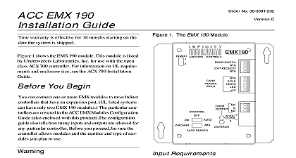
Click for EMX Menu No 30 3001 442 A You Begin can install only one EMX Industrial Unit on a con Before you install this module be sure you are not the number of inputs allowed on any particular Refer to the ACC EMX Modules Configuration also enclosed with this product for details shown in Figure 1 each EMX Industrial Unit Sensor is approximately 3.62 3.25 in 3.62 shown in Figure 4 each EMX Industrial Unit Buffer Board approximately 6.12 1.56 in 2.25 units operate in the same environment as any Infinet The EMX Industrial Unit is designed for flush mounting DIN 1 Dimensions of the of the EMX Industrial EMX 170 Unit warranty is effective for 18 months starting on the the system is shipped can connect one or more EMX modules to most Infi controllers that have an expansion port If you are not which controller to attach modules to refer to the EMX Modules Configuration Guide equipment has been tested and found to comply with limits for a Class A digital device pursuant to Part 15 the FCC Rules These limits are designed to provide protection against harmful interference when equipment is operated in a commercial environment equipment generates uses and can radiate radio fre energy and if not installed and used in accordance the instructions in this manual may cause harmful to radio communications Operation of this in a residential area is likely to cause harmful in which case the user will be required to cor the interference at his own expense sure wiring and installations comply with local state national electrical codes digital apparatus does not exceed the Class A limits radio noise emissions from digital apparatus set out in Radio Interference Regulations of the Canadian De of Communications pr appareil num n pas de bruits ra d les limites applicables aux num de la class A prescrites dans le sur le brouillage radio par le des Communications du Canada Requirements EMX Industrial Unit consumes up to 15 mA at 24 to VDC Manuals Online Bi ktSAdMA01810AllRihtRd Requirements Wire the Sensor for EMX Menu wire the sensor with six conductor 24 gauge wire overall shield and 12 pF ft capacitance between con and 22 pF ft capacitance between one conductor others connected to the shield Anixter 9I2408501 or Anixter 9D240850 non plenum You may ex up to 180 ft of wire from the sensor to the Infinet the EMX Industrial Unit Unpack not damage the packaging material while unpacking should have the following parts EMX Industrial Unit Sensor Module EMX Industrial Unit Buffer Board where required Shielded wire with 6 or 8 conductors not included Wire for External Thermistor optional Infinet twisted pair cable optional Wire for electro static discharge protection not controllers include a built in EMX Industrial Unit board In these cases the port location is shown in controller installation guide Connect Buffer Board to the Infinet if Required sure you disconnect the Infinet controller AC power before you connect any modules the installation guide that accompanies the control to see if a buffer board is required to connect to the If it is required connect the buffer board to the controller as follows otherwise proceed to wire sensor as described in the next section the EMX Industrial Unit Sensor Module to the EMX Unit Buffer Board or to the built in buffer port on the controller itself if applicable see the guide for the controller one wire under each of the following terminals on board and tighten the screws down on them 1 2 3 5 6 2 shows the location of the terminals on the EMX Unit 2 EMX Industrial Unit Terminal Block SHLD Thermistor 2 3 4 5 6 7 8 9 10 11 you plan to use the Service Tool in the EMX Industrial Service Port you can connect the module to the as described in the next section Refer to the installation guide for information regarding cables the two external thermistor wires under terminals and 11 Tighten the screws down on the wires a minimum 14 AWG ground wire maximum ft long to the electro static discharge screw 3 shows the location of the electro static discharge on the bottom of your Infinet controller for an ex port in approximately the center of the panel the other end of the electro static discharge wire solid earth ground at the EMX Industrial Unit buffer board Notice it has a connector on the top Plug the connector the Infinet controller protects the EMX Industrial Unit from electro discharge which could permanently damage the or severely shorten its life Manuals Online for EMX Menu Module to Infinet can connect the module to Infinet but should only do if you plan to use the Service Tool in the EMX Indus Unit Service Port If you connect it when not needed are lengthening your Infinet unnecessarily 3 Back Side of the EMX Industrial Unit the EMX Industrial Unit into the panel Make sure gasket is not twisted and the two side mounting secure the unit to the panel the buffer board or on the controller if no buffer is required insert the other end of each wire from 6 conductor wire under the screw with the matching 1 to 1 2 to 2 and so on and tighten the screw on it 4 shows the EMX Industrial Unit buffer board and labeled positions of the terminals 4 Wiring the EMX Industrial Unit Buffer the positive negative and shield wires under the terminals on the controller Refer to the installation guide for information regarding cables you wired the Infinet to the EMX Industrial Unit you can the Andover Controls Service Tool into the service The service port is a 4 pin Berg type connector on the panel of the sensor To use the service port you have an adaptor that changes from an RJ 11 connec to a cable with the following pinouts 1 2 3 4 of RJ11 Berg Wire Infinet Infinet 5 illustrates the connections from the RJ 11 plug to Berg type adapter to the Sensor Plus Service Jack Block step is OPTIONAL and required only if you expect use the Service Tool in the service port the positive Infinet cable wire under terminal 7 the negative wire under terminal 8 the screws down on the wires the Unit that you have finished wiring it you mount the sen as follows the recommended panel cutout located at the end this installation guide cut out a hole in the panel you want to install the EMX Industrial Unit the shield Infinet cable wire under terminal 9 1 Pinouts for 4 Pin Berg Connector Manuals Online Character Set 6 Stick On Character Set for EMX Menu can order a stick on character set for the buttons on front of the EMX Industrial Unit order part number 6 shows the stick on character set 7 is the mounting template for the EMX Industrial 5 Correct Positioning of Berg Adaptor to Berg Adapter 2 3 4 Adapter Sensor Plus 345 67 891011 11 Plug LapTop Manuals Online 7 Full Size EMX Industrial Unit for EMX Menu Cutout Manuals Online Manuals Online