Andover Controls ACC EMX Modules Configuration Guide

File Preview
Click below to download for free
Click below to download for free
File Data
| Name | andover-controls-acc-emx-modules-configuration-guide-4830926751.pdf |
|---|---|
| Type | |
| Size | 939.05 KB |
| Downloads |
Text Preview
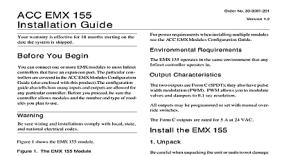
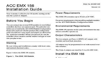
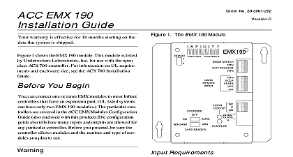
Click for EMX Menu EMX Modules Configuration READ THIS DOCUMENT FIRST No 30 3001 279 1.2 can connect one or more EMX modules to any of the controllers SCX 900 LCX 810 TCX 850 851 Read this document to be sure you select the right combination for your controller Module Configuration can install more than one module on one controller as as you do not exceed the maximum total number of in or outputs allowed on that controller 140 and EMX 190s Are Special count 2 outputs on the EMX 140 modules even if the model has only 1 such as EMX 141 Also the EMX must always be the last output modules on the chain EMX 170 at End of Chain you have an EMX 170 or expect to add one in the future the 170 must always be the last module on the entire chain 1shows the number of base expansion and total in allowed for each Infinet controller 1 Number of Base Expansion Module and Inputs Outputs Allowed for Various Controllers No Base Exp Total Base Exp Total Outputs 850 851 810 900 that the TCX 853 is the same as the TCX 850 also that the EMX 141 counts as two outputs although has only one Inputs Allowed the input modules you can always have a maximum of EMX 160s and one EMX 170 for a total of 17 expan inputs If the modules however consume a total than 110 mA you must add an external power more later Outputs Allowed the output modules you can have up to 8 expansion out on an SCX 900 or LCX 810 controller You can have to 4 expansion outputs on an TCX controller or If the however consume a total greater than 110 mA must add an external power supply more later Modules in Order should first attach all output modules then all input not attach an output module an input module then an output module as this later causes confusion when input and output numbers Board Switches you can have more than one of always have a switch that you set to Board 1 or Board 2 For loca of the switch see the installation instructions for the module must always set the first module of a particular model to Board 1 So we strongly advise that you attach modules of the same model number one immediately the other must set the first output module on the chain to Board the second to Board 2 the third to Board 1 the fourth to 2 and so on matter which model number mod When you start the inputs modules start at again 1 and continue to alternate from 1 to 2 There is only exception to this general rule EMX 190 EMX 190s to Board 1 and Board 2 EMX 190s must always be the last or the last two out modules on the chain Always set the first EMX 190 to 1 and the second to Board 2 no matter what In the of the EMX 190 you must attach one module immedi after the other External Power Needs limited number of modules can be powered on the Infi controller power alone Manuals Online Bi ktSAdMA01810AllRihtRd for EMX Menu each model consumes a slightly different amount of you can combine various sets of modules without external power supply determine the combina by adding the total milliamps the modules consume it is not greater than 110 mA the Infinet controller sup enough power for the chain Below is a list of the of power each module model consumes EMX 140 141 142 143 mA EMX 150 mA EMX 151 mA EMX 160 mA up to two allowed per controller EMX 155 mA EMX 170 mA only one allowed per controller EMX 190 191 192 mA add more modules you need a power supply that de 24 VDC and an adequate current output rating for total number of amps the chain consumes 2 shows some combinations allowed with internal only This table is not an exhaustive list of combi however it does illustrate why you may want to external power External power allows you to add more modules see Figure 1 below 2 Sample Combinations of Modules Allowed Internal Power Supply Alone Combo Combo 3rd Combo Combo of any EMX except 151 190 170 EMX 150 EMX 160s EMX 170 EMX 155 EMX 190 EMX 160s EMX 160s you use external power you attach one external source to a the first module requiring external The power source then serves all modules you after that up to the next external power supply that module and only that module of the group you change the position of a jumper that indicates you using external power See the instructions that go with module to find out exactly where the jumper is located the particular module you are installing 1 shows a sample configuration on an SCX 900 1 Sample Configuration of EMX Modules on an SCX 900 Controller if you have one output 141 count outputs for the 15 16 assign these input and numbers very carefully covered in the CX Programmer Guide 150 1 Outputs 9 10 150 2 Outputs 11 12 140 1 Outputs 13 14 190 1 Output 190 2 Output 160 1 Digital Inputs 160 2 Digital Inputs 17 25 170 Input 33 Manuals Online for EMX Menu you are using external power before you actually pow on the controller you must be sure that the power goes the controller and the extra modules at the same time do this by wiring the external power supply to the same that enter the AC power connection on the controller when you close the AC power connection the power to both the controller and the modules simultaneously 2 Wiring AC Power to Both Controller a TCX or LCX 810 and Modules 2 shows the wiring of the external power supply to an LCX 810 or a TCX 850 or other TCX controller these controllers each require 24 VAC power to proper operation wire the external power supply to AC power source as shown 3 shows how you would wire an SCX 900 3 Wiring AC Power to Both SCX 900 and Modules VAC VAC Primary VAC Secondary VAC VAC any VDC VAC VDC VAC wiring is much simpler but you are applying the concept of sending power to the controller and mod simultaneously Manuals Online for EMX Menu Manuals Online