Andover Controls Continuum IO Modules

File Preview
Click below to download for free
Click below to download for free
File Data
| Name | andover-controls-continuum-io-modules-5341028769.pdf |
|---|---|
| Type | |
| Size | 1.10 MB |
| Downloads |
Text Preview
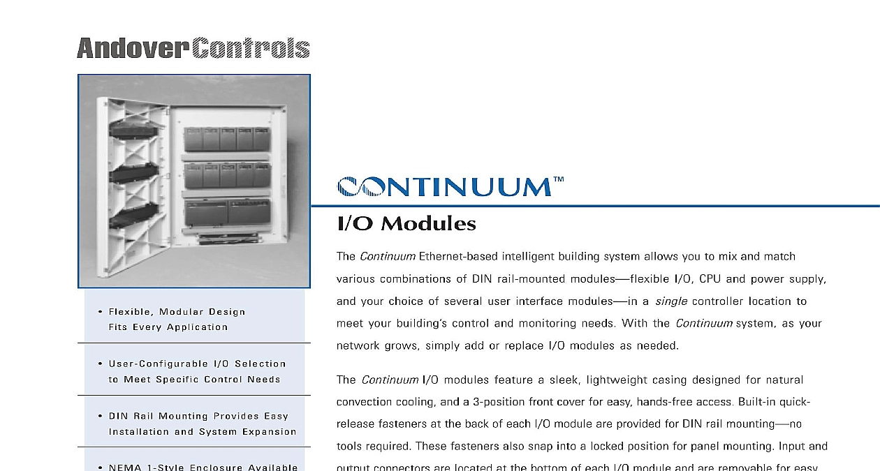
cid 215 NTINUUM Modules Flexible Modular Design Every Application User Configurable I O Selection Meet Specific Control Needs DIN Rail Mounting Provides Easy and System Expansion ContinuumEthernet based intelligent building system allows you to mix and match combinations of DIN rail mounted modules I O CPU and power supply your choice of several user interface modules a single controller location to your building control and monitoring needs With the Continuumsystem as your grows simply add or replace I O modules as needed ContinuumI O modules feature a sleek lightweight casing designed for natural cooling and a 3 position front cover for easy hands free access Built in quick fasteners at the back of each I O module are provided for DIN rail mounting required These fasteners also snap into a locked position for panel mounting Input and NEMA 1 Style Enclosure Available connectors are located at the bottom of each I O module and are removable for easy access and maintenance All Continuummodules are designed for mounting in an Three Position Front Cover for Access NEMA 1 style Continuumenclosure ContinuumI O modules communicate with the ContinuumNetController CPU module Andover LON communications Like all Continuummodules the I O modules slide via built in connectors on either side so network expansion is quick and easy power transmission and communication signals feed through these connectors For convenience in certain applications such as door control or lighting control single module or groups of I O modules can be remotely located and connected using cable and powered from a local 24 VDC power supply Each I O module its own push button for quick and easy network commissioning Built in Quick Release Tools Required Removable Input Output for Easy Installation Slide Together Power Connections Optional Remote Mounting Push Button Network Manuals Online ContinuumI O modules share the following specifications Environment to 120 0 to 49 10 to 95 RH non condensing x 6.7 x 2.5 96.5 x 157.5 x 63.5mm lbs 0.34kg on DIN rail or wall mount using attached clips 1 style enclosure available Backup ContinuumUPS power supply Interface communications with ContinuumCPU module of bus media RS 485 or FTT 10 for remote I O mounting Error Checking Standard CRC 16 AB AB AB AB ATTERY Speed 39k baud Length Media ft 610m Repeater required for longer distance or after 32 nodes twisted pair cable 120W termination required at ends of the LON network when modules are mounted Speed 78k baud Length to 8858 ft 2700m bus topology to 1640 ft 500m free topology required for longer distances to LON free topology documentation plug in connectors on left and right sides allow Continuummodules to be directly to each other or remotely connected via approved cable Media Connections MCU with internal ROM EEPROM and SRAM LISTINGS LISTINGS LISTINGS LISTINGS LISTINGS 916 FCC CE Manuals Online MODULE P E C I F I C A T I O N S UI 8 10 Continuum universal input module provides 8 universal inputs software configurable as voltage thermistor digital counter point types Each point can also be configured as a supervised input for security monitoring providing separate of alarm and trouble conditions This module is a perfect choice for any mix of temperature pressure flow status points similar inputs in a control system with a 0 5 volt input range and 10 bit A D conversion UI 8 10 10V model is also available for 0 10 volt applications It provides the identical point type selection but is equipped with voltage divider DIP switches on each input allowing each to be configured for a 0 10 volt range Consumption watts at 24VDC max when provided by Continuumpower supply module Protection resettable fuse with transient voltage suppressor TVS and reverse polarity protection of Inputs Universal inputs 10 bit resolution Types Thermistor Digital Counter and Supervised Protection AC DC allowed to any single input 40V TVS on each input UI 8 10 10V model only Impedance 0 5V 0 10V MW KW w pullup disabled 10 KW w pullup enabled Connections 13 position removable terminal block Counter LEDS SWITCHES LEDS SWITCHES LEDS SWITCHES LEDS SWITCHES LEDS SWITCHES Indicator LEDS Switches Type Width Type 0 5V volts mV mV FSR 0 10V volts mV mV FSR Type III Thermistor KW to 230 34 to 110 to 100 range to 38 to 100 range to 38 0.20 typical typical 1.0 Closure Hz max mS min Indicator Indicator Indicator or Double Resistor Supervision Parallel or Series Circuit O D E L S Universal inputs 0 5 Volt input range Universal inputs 0 10 Volt input range Manuals Online MODULE DI 8 Continuum digital input module is used for cost effective sensing of multiple dry digital inputs in applications such as status monitoring or alarm point monitoring The DI 8 has eight digital inputs can be software configured to a digital contact closure or 0 5 volt input or counter signal Counter frequency is 10Hz on all eight inputs In addition high counting up to 10KHz max is available via a DIP switch on Channels 1 and 2 for high speed metering and industrial bipolar transorbs on all eight inputs protect against high voltage short duration transient events The DI 8 is designed to dry contact inputs or 0 5 volts but can withstand up to 24 VAC DC continuous voltage on four channels Consumption watts at 24VDC max when provided by Continuumpower supply module Protection resettable fuse with transient voltage suppressor TVS and reverse polarity protection P E C I F I C A T I O N S of Inputs Digital inputs Types or Counter software selectable Protection AC DC applied to 4 channels max 40V TVS on each input Impedance pull up resistor referenced to 5 volts Connections 13 position removable terminal block Type Width closure or 0 5V input min Type 1 and 2 in HI speed mode selectable via dip switch closure or 0 5V input 3 through 8 and Channel 1 and 2 in LO speed mode Width Width max min max min LEDS SWITCHES LEDS SWITCHES LEDS SWITCHES LEDS SWITCHES LEDS SWITCHES Indicator LEDS Switches Status 1 8 Indicator Indicator Indicator Status Indicator Closed circuit ON Manuals Online MODULE P E C I F I C A T I O N S DI 6 AC Continuum digital AC input module has six digital AC inputs for cost effective ON OFF status indication of fan starters solenoid valves control relays or external power supplies and similar applications that require a quick and easy way to voltage The DI 6 AC monitors the absence or presence of AC v


